

Introduction: DIY Variable LED Panel (Dual Color)


Improve your lighting by making an affordable DIY Rechargeable LED Panel! Equipped with Dual Color brightness adjustment, this project gives you the flexibility of adjusting your light source's white balance to match your surrounding's ambient light. LED Panels are one of the essential tools for filming. Unlike softlight setups, LED panels are very versatile, portable enough to fit in your backpack.
Watch My Full Video Tutorial:
FEATURES:
- Dual Color Adjustment (3000k-6500k)
- Brightness Adjustment (Without Flicker)
- Rechargeable & Can Run On Grid Power
- Runs On 18650 Li-Ion Vape Batteries
- Adjustable Ball Joint Clamp
Step 1: Parts & Materials


PARTS & MATERIALS:
- 6500k White LED Strips (Select White - https://bit.ly/2V2kDy7)
- 3000k Warm White LED Strips (Select Warm White - https://bit.ly/2V2kDy7)
- LM2596S DC-DC Buck Converter (2x - https://bit.ly/2V2kDy7)
- LCD Voltmeter (2x - )
- 3S Li-Ion BMS Module (https://bit.ly/3bPYGJq)
- 3S 18650 Battery Holder (https://bit.ly/2JETImL)
- 18650 Li-ion Batteries (3x - https://bit.ly/2V2kDy7)
- 12V 2Amp Power Brick ( ) - DC Jack (https://bit.ly/2x6IswC)
- Switch - 1/4" Nut
- Bike Camera Mount ( )
Step 2: Prepare the Picture Frame
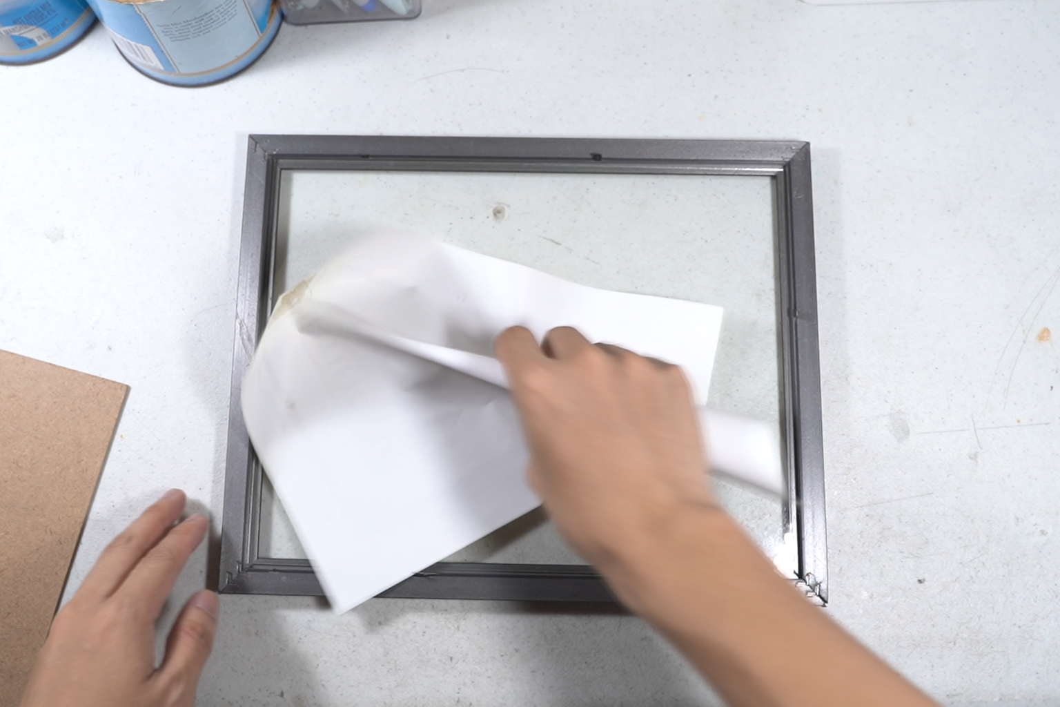
We will be using a picture frame as our project's enclosure. Remove the picture and the glass that comes with the frame. Removing the glass makes your project less fragile and much lighter.
Step 3: Paint the Frame & Panel


You can personalize your LED Panel by spraying paint on the frame and on the wooden panel.
Step 4: Cut the LED Strips


LED strips can be cut down into segments and can be soldered again afterwards. There are cut lines on where you can cut them. Base the length of your cuts from the horizontal length of your picture frame's width.
Step 5: Mount the LED Strips


Peel the protective layer of the adhesive at the back of your LED strips and mount them on your frame's wooden panel. The white and the warm white LED strips are sequenced alternately. I started mine by mounting the white LED strips, then the warm white LED strips, then the white LED strips and so on...
Step 6: Wire the LED Strips


1.) Using a bare solid wire, solder all the negative pads of the strips together into one line, this would be your common ground.
2.) Using a separate line of bare solid wire, solder all the positive pads of the white LED strips together.
3.) Using a separate line of bare solid wire, solder all the positive pads of the warm white LED strips together.
Take Note:
You should now have three power lines, one for the common ground, one connecting all the positive pads of the white LED strips and one connecting all the positive pads of the warm white LED strips.
Step 7: Drill Through Holes


You can drill holes through then wooden panel to route your wires from the front to the back. This way, you wouldn't have to run your wires around the outer rim of your frame.
Step 8: Follow the Wiring Diagram

Here's a simplified diagram for wiring the components.
Battery Configuration: For this project, I'm using three 18650 lithium-ion batteries connected in series. 18650 batteries are very common, they are often used in vapes and in flashlights. These batteries usually have 1,500mAh - 3,500mAh of capacity and has an operating voltage of 3.2v - 4.2v. Lithium batteries are perfect since they have a high energy density to size ratio and have steep discharge curves. When three of these are connected in series, you get to have a battery pack with an operating voltage of 9.6v-12.6v (11.1v nominal).
BMS:
Lithium batteries are dangerous when shorted, over discharged and overcharged. They can overheat and release flammable fumes once it reaches its maximum conditions. As a result, lithium batteries receive its infamous reputation of blowing up in flames. A BMS module or a battery management system, is a circuit that cuts of power when, one of the cells reach its minimum or maximum voltage or when too much current is drawn or introduced. This prevents the danger of explosions. Some BMS modules come with balance charging, this ensures each cell reaches its maximum charge to achieve a battery pack's maximum charge. The one I used in this project has all of the features except for the balance charging, this means if you choose to buy the exact BMS I used, you might have to balance charge the batteries once in a while to achieve the maximum capable charge capacity
DC-DC Converter:
I'm using the LM2596S DC-DC buck converter to control the output voltage for brightness control. The circuit is a type of switching regulator. Unlike linear regulators, switching regulators operate at high efficiencies and does not convert the excess in power as a form of heat. Light flickering is barely a concern in this module since it has a high modulation frequency of 400kHz.
LCD Voltmeter:
In this project, the LCD voltmeter is used to monitor the output voltage of the regulator that feeds the LED strips. This way you could use the voltage reading as a basis for setting your brightness level. Unfortunately you wouldn't get reading of brightness in % but rather get in in voltage. I plan to build an MCU based LED panel in the near future.
Step 9: Desolder & Replace the Trimmer Resistors


The DC-DC converters come with adjustable 10k Ohm multi-turn trimmer resistors. The problem with these specific adjustment knobs in specific, is that it requires a screw driver for adjusting them. For me to be able to tune the regulator by hand, I replaced both DC-DC converter's trimmer resistors with its 10k Ohm equivalent potentiometers.
Step 10: Mount the Components

You can use superglue to mount the electronic components on the wooden panel, this way, you wouldn't have to use the drill and some screws.
Step 11: Wire the Components


Grab your soldering Iron and wire them up! I suggest using guage 18 wires.
Step 12: Install the Batteries

Step 13: Adding the Mount


I bought myself a ball joint camera bike mount. You can use the mount on the panel by attaching a 1/4" nut on the very center of the wooden panel. I used a lot of superglue to secure it in place.
Step 14: Makeshift Pole Stand


A cheap project calls for a cheap stand. It's really sturdy and has a very small footprint. A few years ago, I came up with this idea to hotglue a PVC pipe at the center of an icecream container as a pole stand. I used sand as extra weight to prevent the stand from tumbling down. On the other hand, I got my pole from an Aluminum curtain rod I had left from a previous project.
Step 15: How to Use It

Using it is pretty simple. You have a switch for the power and two control knobs for controlling the brightness of the warm and cool LEDs. The LCD voltmeter displays the voltage of each LED color, you can use it as a reference for your brightness settings. You can use the two knobs to play around with different light intensities. Mixing the two LEDs would give you different combinations of intensity and white balance.
Step 16: How to Charge It


To charge it, simply find a 12V (2A) power brick and connect it to your LED panel's DC jack. This should charge your batteries directly without using a bay charger. The BMS module cuts of the electrical feed once the battery has reached it's maximum charge. Although, there's no way of knowing whether the battery has finished charging in this specific setup. There's a way around this. I suggest buying an iMax hobby grade RC car charger or perhaps grab a laptop powerbrick and buy an adjustable CC-CV battery charging module.

Second Prize in the
LED Strip Speed Challenge


