

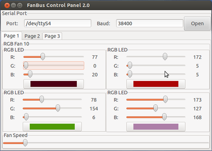
Introduction: FanBus Digital Fan and LED Interface for PC


The bus uses a simple TTL-level serial signal in half-duplex mode. A MAX232 on the distribution board adjusts the RS-232 input from the PC to microcontroller-compatible levels. A diode and pull-up resistor are used to convert the full-duplex UARTs (and MAX232) into half-duplex. The diode is responsible for pulling the line low when the Tx pin drives low. This allows a large number of devices to be plugged in at the same time without any damage to the serial hardware. With a properly formed protocol there are no collisions or communication problems.
Every device has a pre-programmed/reprogrammable address stored and loaded from EEPROM that it uses to identify itself.
The devices I built are more RGB fan controllers which are modified from the original design (eliminate the MAX232 and compact the board a bit to save space). They have the same functionality (4 RGB LED's with 256-level PWM, 256-level hardware high-speed PWM with drive transistors for the fan, RPM counting and readout from the fan's sensor wire). Like the original, the new design is also based around the Atmel ATMega168 AVR microcontroller and the board has a programming header for in system programming.
With the PC software and the fans installed, anything is possible. You could script them to notify you of new e-mail, you could have them change color based on the temperature or weather report, you could have them fade throughout the day...or you could flash them to music:
Step 1: Gathering the Parts


The parts list is essentially the same as before.
For the 5-port FanBus to Serial board:
1x MAX232 (I recommend a socket too)
1x Diode
1x 1K Ohm Resistor
4x 1uF Capacitor
6x 4-pin header (1 for power, up to 5 for FanBus devices)
1x 3-pin header
For one FanBus RGB Fan Controller:
1x ATMega168 (I recommend a socket on this as well)
1x 4-pin header
2x 3-pin header (or one 2x3 header, for ISP connector)
12x 300 Ohm Resistor
1x Diode
1x 1uF Capacitor
2x 10K Ohm Resistor
3x 1K Ohm Resistor
1x 1116 Transistor (or equivalent)
1x 1616 Transistor (or equivalent)
2x Jumper (I just used clipped resistor leads)
For one RGB Fan:
1x 4-LED PC fan with sensor (yellow or white) wire
4x 4-pin common-cathode RGB LED (diffused)
4x Length of 4-conductor ribbon cable
1x Roll of transparent tape to hold it together
A 6x6 inch, single sided copper clad board should be plenty. I used one 6x6 board to make 3 FanBus controllers, one FanBus adapter, my original RGB Fan Controller, and a LocoNet to Serial adapter for a train set. One piece of PCB goes a long way!
You will also need a laser printer to do toner transfer (I used my HP LaserJet 5M, got it for $10 at a university garage sale and it's perfect!). I recommend glossy or semi-glossy paper. I used the back of some newspaper ads, save the ones that are already 8.5x11" size paper as you don't even have to cut them to size, just feed it into the printer and go. You will also need a clothes iron (preferably one you don't use for clothes anymore) and a bottle of etchant (I used ferric chloride, $10 at RadioShack for a pretty large bottle that will last you a while). To cut the boards down to size I used a Dremel with cut-off wheel.
Step 2: The Board: Printing and Transferring


To make the boards, I used the common laser printer toner transfer method. It produces decent quality boards from CAD files and is easy enough to do yourself without buying much. You need a laser printer (I used an HP LaserJet 5M) and paper that is smooth enough for the toner to transfer from.
The Eagle files as well as PDFs of the boards will be available on my Google Code project page:
http://code.google.com/p/rgbfan/
Getting the right paper can be tough, you want something thin and glossy but not so thin it jams the printer (this happened with really thin newspaper). I used a thicker paper often used for advertisements, it sometimes even comes as standard 8.5x11" paper so if you get these in your junk mail save them! Just stick one in the printer (print on the least-printed side, though if it was printed in ink it will still work, ink does not transfer). I used Eagle to print the boards (not mirror imaged or upside down, the transfer mirrors it already).
After printing, cut out the design and clean your PCB with an abrasive pad until it is shiny, wipe it off so that no dirt or residue affects the transfer. Preheat the iron (I put mine on HIGH but mine is a small travel iron) and then set it down on the board (copper side up) to warm up the board. Wait 5-10 seconds if your iron is hot and then remove it. Let the board cool a bit until it is warm but not so hot you can't touch it. Then lay the paper face down on the copper and press the iron down with force. Hold it for 5-10 minutes, adjusting your position to evenly heat the entire paper. After this, the board should be too hot to pick up, so let it cool down (and if it is cool already, put the iron back on as it should get hot to transfer properly).
Fill a container with steaming hot water (I found it works best) and then submerge the board with the paper attached into the water. The water will soak into the paper and you should be able to see the traces through the paper. Once it is completely soaked, wait a minute or two and then slowly start peeling the paper away. The traces should remain on the board. If the paper splits, just pull it off in pieces until all the gaps between traces are clear. Don't scrub too hard on the traces themselves, when you take it out of the water there will probably be paper threads still attached to the traces, just trim them with a sharp knife if they hang off the traces.
If there are any breaks, take a black Sharpie (I used a blue one before and it didn't work very well, black seems to work better) and draw over the breaks. The black ink from permanent markers is strong enough to resist toner so you can use it to touch up small flaws. If the breaks are too large, you can use Acetone (nail polish remover) or an abrasive pad to clean the toner off and start over.
Step 3: The Board: Cutting, Etching, and Cleaning
After transferring and touching up the traces, I cut the PCB out of the larger sheet with a Dremel. After cleaning the board up, drop it in the etchant solution and let the etchant eat away the copper until only the traces are left.
Once etched, wash the board in warm water to clean the etchant off and then use acetone (nail polish remover) to remove the toner and expose the copper traces. I also used Goo Gone because the acetone was leaving black streaks on the board. Once the board is clean it should be a bright copper color again.
Next, the board needs to be drilled. I used a drill stand and a regular single-speed drill with a small drill bit to drill the tiny holes. Drill out each hole and make sure to leave a ring of copper to solder to, don't drill the hole too big or it will be harder to solder.
Step 4: Assembling the Boards
After the PCB's are completed, it's time to solder all the parts in. The diagram below identifies what parts go where. I recommend using an IC socket for the MAX232 and ATMega168 chips to protect them from the heat as well as allow them to be removable.
You can either program the ATMega168's on a breadboard before board assembly or use the onboard ISP header to program them once the boards are assembled. I would recommend programming them before installing them in your PC because it can be tricky to get the programming cable into tight spaces.
Get a copy of the code from the Programming step to flash your chips.
Step 5: Modifying the Fan


In addition to creating the boards, I modified regular LED fans with RGB LED's to be used with the boards. I had to pry the existing LED's out of the fan with a small screwdriver and then desolder them from the wires. I taped up the wires to prevent them from shorting and then installed the RGB LED's in their places.
To prepare the RGB LED's, I held them in helping hands, bent the leads close to the base, and soldered on a 4-pin ribbon cable. The LED's were then press-fit into the holes in the fan and I used transparent tape to attach the ribbon cables to the fan body, then bundled them together with more tape where the fan's power cord comes out so that all the wires can be bundled together.
Note which wire is ground when soldering to the RGB LED's. If you know which one is ground you can find the rest, the pinout is Red Ground Green Blue. Also, if you have water clear LED's, it is a good idea to sand them with fine sandpaper until they have a frosted, diffuse look. The clear LED's do not blend colors well unless they are diffused by sanding or by other means.
Also note the fan mounts on your PC case. If the case has special mounting hardware, you may have to install the wires and LED's in a different orientation so that they don't interfere with screws or mounting tabs. If there isn't enough space around the side of the fan to get the wires out, you may have to cut a notch in one of the fan corners to run wires through.
Finally solder the LED wires to the controller board noting the ground pin. You will have to flip the red LED and ground wires (the board is arranged Ground Red Green Blue while the LED's are Red Ground Green Blue). Also solder the fan in, the center pin is red (+12V), the one closest to the LED connector is ground, and the one on the far edge of the board is sensor. You can solder in a 3 pin header instead if you don't want to cut the fan plug.
Step 6: Installation


Installation depends a lot on what case you have and how organized it is. You will need to find a place to put each controller board and also a place to put the distribution/adapter board. I put the controllers in empty drive bays where the fans are mounted. For the side fan, I taped the controller board under the fan on the side panel (I put a piece of black paper under it so it isn't as noticeable through the window).
For the adapter board, I taped it to the bottom of my case for easy access to the power supply and ran a ribbon cable to my serial port card (disconnected the second port and plugged in the ribbon cable instead).
To make the FanBus cables I used four conductor phone cable and female break-away pin connectors in 4-pin segments. The pinout is Data Ground +5 +12. Looking at the adapter board (with the MAX232 at the top) from left to right, it is the reverse (+12 +5 Ground Data). Looking at the controller with the FanBus connector at the bottom, from left to right, it is Data Ground +5 +12. Plug it in correctly or you will destroy the ATMega168 and possibly more. The adapter's power connector (with MAX232 on top, from left to right) is +12 Ground Ground +5 (matches the 4-pin Molex connector on ATX). The serial connector on the adapter (with MAX232 on top, from top to bottom) is Ground, Rx, Tx.
Step 7: Programming!

https://github.com/CalcProgrammer1/FanBus-Fan-Controller
I also wrote a Visual Basic control program that should work for up to 3 RGB fans. It is my first VB application so it probably isn't very well coded. I will re-write it once I finalize the FanBus protocol (right now it's using a modified version of my original protocol which isn't perfect).
The GTK+ code from my original fan controller is also available and can be modified to work with the FanBus fan controllers which use almost the same protocol.
However, the real interesting part is using Processing to make cool audio visualizations with the LED's. Processing has a library called Minim which provides tools for analyzing audio signals. I wrote a script based on one of the examples that uses the FFT algorithm to produce a frequency graph of the sound and then use that data to flash the LED's. It reads the default input device so you need to set the default input to "Stereo Mix" or whatever else the internal loopback connection is called on other sound cards (mine's Realtek). Then just play music through your favorite app and the lights should flash.

Participated in the
MakerBot Challenge


