

Introduction: Servo Tester and Sequencer


Having started yet another project involving servos, once again I found myself the facing same problems. I've built the hardware and I want to test it by exercising the servos. There might be:
- a dozen servos
- you want them to move to different positions
- you want to limit their range of movement
- you want to limit their velocity or acceleration
- you want to remember and playback a sequence of positions
- maybe
- you want to control them from a PC
- you want to trigger a sequence with a signal or button
This project describes such a servo-sequencer. It's quite cheap. These are the prices I paid but things are getting more expensive every day.
- Arduino Nano £2.80
- OLED display £3
- rotary encoder £0.75
- maybe (depending on what's in your junk box)
- battery holder
- stripboard
- header pins
- knob
- on/off switch
You can use an external sensor or a push-button to trigger playback of the stored sequence. That would useful for halloween props and the like.
The software contains code which you might find useful in other projects
- driver for OLED
- driver for rotary encoder
- menu software
- servo ramping
Step 1: Building the Circuit


12 servos are connected to pins D2 to D13 of the Arduino Nano.
The OLED display is available from multiple suppliers on eBay, Aliexpress, etc. I bought a 1.3" screen, 128x64 pixels. Make sure you choose one that uses the SH1106 controller and has an I2C interface. A typical advert says
- 1.3" OLED LCD 4Pin Display Module IIC I2C 128x64
The I2C interface needs pullup resistors on the SDA and SCL pins. It operates at 3.3V which you can get from the 3.3V regulator in the Nano (the curent is typically under 20mA but can rise to 80mA if all the pixels are lit; the Nano can supply 50mA at 3.3V). SDA and SCL are connected to A4 and A5 which are the hardware I2C pins of the Nano.
The rotary encoder is connected to A0, A1, A2 which are configured as digital inputs with pullups.
The circuit is powered from 4 AA cells nominally giving "6V" - actually, it's 5.5V to 6.5V. The "6V" is connected to the "Raw" input of the Nano. You shouldn't power the servos from the 5V provided by the Nano - the current draw is too high.
The Nano's regulator will drop the "6V" to the "5V" that the Nano needs. (Yes, I know that the regulator's dropout will reduce the "6V" to less than the 5V that the Nano supposedly wants but the ATmega328P uses 3.3V internally and the brownout detector seems happy. You can put 4V into the Raw input and the Nano will still work.) Surprisingly, the regulator will pass current backwards so if you switch off the battery and connect a USB lead you will power the servos (at a reduced voltage). The current drawn by the servos from the USB might be high enough to destroy the protection diode near the USB connector - it's a pain to repair. So don't plug in a USB lead and the servos unless you have the battery switched on. To prevent the diode being destroyed, you could put a 10ohm resistor in the Raw input line which will limit the "backwards" current without dropping too many volts (but I didn't bother because I only found the problem after I'd built the board).
Depending on what sort of battery holder you use, you may need an on/off slide switch. I used a battery box that has a built-in switch and holds 4 AA cells.
I tested the circuit on a solderless breadboard then transferred it to stripboard. The layout I used is shown above. The board is shown from the component side. In my diagram, the copper of the stripboard is shown in cyan. Red lines are wire links on the stripboard or flexible wires joining the parts together. It's a bit tricky soldering the header strips for the servos. I cut a row of breaks in the stripboard for the 6V pins and soldered a wire along the row. On reflection, it would have been much easier to use perf-board.
Notice that I soldered a row of header-pins in upside down on the "TxD" edge of the Nano. On the "Raw" edge I only soldered a few of the pins (shown as squares); the other holes have flexible wires.
The rotary encoder is quite tall so I raised the OLED on tinned copper wire "stilts" which I thought looked nicer.
The PCB is fastened to the battery box with foam pads ("sticky-fixers").
I made a cover out of 1mm polystyrene sheet.
Step 2: Alternatives


You can add a push-button to trigger Play. It connects A3 to ground. If you fit a button then you should un-comment the HasRunBtn #define:
#define HasRunBtn
The Play button will only work when the main menu is being displayed. It is disabled in sub-menus.
The Play button is mounted on a daughter board which is raised in stilts to the height on the main panel.
You might want to trigger Play from an external signal, for instance you have a halloween prop that is operated by a PIR sensor. If so, you can connect it to A3.
It's such a simple circuit that I built it on stripboard - I'm too impatient to wait for a PCB. But I realise that some people just don't like stripboard. I've attached gerbers if you're determined to buy a PCB. The board has holes for a slide switch as part of a break-off tab. The board is sized to fit the battery box I used which has its own switch so you'd break off the tab. There is no standard for slider switches but the switch you have can probably be hacked to fit.
At first I considered using a simpler battery holder without a switch. It's smaller so I imagined servo pins along one edge, soldered onto the header-pins of the Nano.
I built the box from polystyrene sheet in about an hour. Perhaps you'd prefer to 3D-print something.
Step 3: The Software

Put all the files (below) in a single folder called "ServoEdit" and double click on the INO file. I presume you know how to upload programs to an Arduino; if not, there are lots of Instructables.
Turn off warnings. My code produces a lot of warnings which I find excessive and unhelpful. In the Arduino IDE (ver 1.8 or higher) select the File|Preferences menu item to open the Preferences dialog. Set Compiler Warnings to "None". Close the dialog.
The units are:
- · ServoEdit.ino: the main program
- · SimpleSH1106.cpp: OLED library
- · servoedit3.cpp: save to the EEPROM
- · servoedit4.cpp: servo driver

Step 4: User Manual

If you have built the circuit and simply want to use it, this Step is a User Manual. If you're interested in modifying the software, also read the Steps after this one.
The software drives up to 12 servos. You can use the Setup menu to select how many servos are in use. Each servo has certain parameters which
- the pin number
- the range of movement
- Vmax - the maximum velocity
- Amax - the maximum acceleration
- the group
A servos always starts off "detached" - no command pulses are sent to it. When you set its position, it becomes "attached" and command pulses are sent to it. When a standard servo is detached, it does not hold its position - the motor is turned off. (Some "digital" servos always hold their position.) When you are developing a robot, it often happens that you make a mistake and the legs get tangled or whatever - the servos start straining and can eventually damage their gears. If you hold you down the knob for one second then all the servos will detach and the servos will relax.
Each servo also has a "current" position and a "target" position. The Position menu allows you to set the position (and target). The servo moves instantly to where you tell it.
When you run a stored program (sequence), the program sets the target positions of the servos. The servos will move to the target limited by the maximum velocity and acceleration you've specified. You can tell the program whether it should proceed to the next line of the program or wait until the servo(s) have reached their targets(s).
If a servo is controlling a joint with high inertiam when the servo moves from where it currently is to a target position you it want to
- accelerate at Amax
- coast at Vmax
- decelerate at -Vmax
The graph of velocity has a trapezoidal shape. Velocity ramps-up, stays constant then ramps down. So it's known as "Ramping".
Servos can be assigned to a "Group". A Group of servos move together. For instange a Group might be the servos for the joints of a leg. You want the servos to all arrive at their target positions at the same time. Groups and Ramping are described in detail in my Servo Ramping Instructable.
"Group 0" means that the servo doesn't belong to a group. All Group 0 servos move independently.
The Learn menu allows you to save all the current servo positions and parameters to EEPROM. The EEPROM can hold up to 341 program lines. Usually one line is one servo position but some extra lines are needed for the servo parameters.
The menus are arranged in a tree. You turn the knob of the rotary encoder to choose a menu item then press the knob to select it.
- Position set servo position
- Adjust position
- return to main menu
- Learn learn all current set servo positions
- Finish:
- learn all current servo positions (wait until Finish)
- Finish Delay:
- choose delay
- learn all current servo positions (wait until Finish then further delay)
- Delay:
- choose delay
- learn all current servo positions (wait fixed delay)
- NoDelay:
- learn all current servo positions (no delay)
- Cancel:
- return to main menu
- Edit
- cyclethrough sequence
- edit step values
- Quit
- Delete
- cycle through sequence
- delete step
- Quit return to main menu
- Clear
- Clear All clear all EEPROM and servos
- Clear Mem clear all EEPROM
- Cancel
- Play execute learned servo positions
- Setup adjust servo parameters
- Choose Servo
- Pin:
- set pin number
- Min:
- set min servo position
- Max:
- set max servo position
- Vmax:
- set max servo velocity
- Amax:
- set max servo acceleration
- Group:
- set servo group
- Num servos Add / delete servos
- Total
- set number of servos
- Relax All
- all servos disconnected
- Button held down
- Relax All
Step 5: The Display

The display is a 1.3" OLE running at 3.3V which is controlled by an SH1106 chip via an I2C bus. (SPI versions are available but ignore them for this project. Some displays seem to have the pins in a different order. Check them.)
I needed a small library so I used my "SimpleSH1106". It is described here and here.
The SH1106 has a built-in buffer with one bit per pixel. It is arranged as 128 columns by 7 swathes (other sizes are available). Each swathe is 8 pixels high with the lsb at the top. In the SH1106 documentation, swathes are called "pages" but "swathe" is the standard term in computer graphics. The smallest unit you can write is one byte - a column of 8 pixels starting on an 8-pixel boundary.
My library has no screen buffer on the Arduino so all the commands are based on writing whole bytes to page columns. It's less convenient but you gain 1k of RAM.
The Atmel328p has a built in I2C driver connected to pins A4 (SDA) and A5 (SCL). SDA and SCL need pull-up resistors; the built-in I2C driver uses the Atmel328p weak pull-ups of around 50kohm. The 50k pull-ups work at low speed but the rising edges are not fast enough for high-speed so I've added 3k3 pull-ups to the 3V3 pin of the Nano.
The following commands are available:
- void initSH1106 initialises the SH1106 registers
- void clearSH1106 fills the screen with 0 bytes (black).
- void DrawByteSH1106 draws a single byte (a column of 8 pixels).
- int DrawImageSH1106 draws an image.
- int DrawCharSH1106 draws a character.
- int DrawStringSH1106 draws a string.
- int DrawIntSH1106 draws an integer.
Images and fonts are declared in program memory (PROGMEM). A Windows program is available to create fonts and to convert a BMP file into a run-length-encoded image for SimpleSH1106.
The DrawStringSH1106 function draws a string which has been defined using the F() macro. The F() macro stores the string in PROGMEM and hence saves RAM space.
Step 6: The Rotary Encoder


I've decided I rather like rotary encoders for simple user-interfaces. You turn the knob to choose a menu item then press the knob to select it.
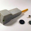
The encoder I used is widely available on eBay - search for "rotary encoder" and look for one like the photo. It has 24 detente positions and for each "click" it produces a complete cycle of quadrature signals. Other encoders may produce other outputs and you would need to write your own encoder function.
The WaitForEvent() function waits for an encoder event and returns a TMyEvent value:
- meClick: the user has pushed the knob
- meWheelMove: the user has turned the knob
- WheelDelta now contains +1 or -1
- meCommand: (optionally) the PC has sent a serial command
The CheckEncoder() function calls Quadrature() to get input from the encoder pins and converts them into up/down counts. It does so using a Finite State Machine which deals well with contact bounce.
It might be better if the encoder worked from an interrupt rather than by polling. The current code works well. and I can't be bothered to change it.
Step 7: The EEPROM

An ATmega328P has 1024 bytes of EEPROM.
The EEPROM is divided into 341 "Triplets" - 3 bytes each (little-endian). Each Triplet contains a single entry of the user's program. The memory layout of Triplets is (in binary):
ssss0ttttttttnnnnnnnnnnn  set target of servo ssss to nnnnnnnnnnn + 500 microseconds (500..2547) then wait
    tttttttt/10.0 seconds
ssss1000pppp0nnnnnnnnnnn  set min position = nnnnnnnnnnn + 500 microseconds (500..2547) ; pin = pppp
ssss1010gggg0nnnnnnnnnnn  set max position = nnnnnnnnnnn + 500 microseconds (500..2547) ; group = gggg;
ssss1100vvvvvvvvaaaaaaaa  Vmax[ssss] = vvvvvvvvvv uS per interval; Amax[ssss] = aaaaaaaaaa/10.0 uS
    per interval;
111111111111111111111111  end of memory
Triplets can be "executed" to run the stored "program". Initially there is assumed to be 1 servo; as the program is run, a servo is added for each different ssss that is seen. Each new servo is assumed to be
- max velocity = 0
- max acceleration = 0
- min position = 500 microseconds
- max position = 2500 microseconds
Those parameters can be changed by the program as it is run.
Triplets that set the target of servo actually move the servos. A "Target" Triplet sets the target position of a servo and hence is specially important. In the menu they are called "Steps". Target "Steps" are numbered from 1 to n.
The servo's maximum velocity and maximum acceleration can be specified. If they are set to zero then the servo will move to the target position as fast as it can. Otherwise the graph of velocity has a trapezoidal shape. Velocity ramps-up, stays constant then ramps down.
- tttttttt = 0..100 means wait for tttttttt/10.0 seconds
- tttttttt = 128..228 means wait for completion then wait (tttttttt-128)/10.0 seconds
Step 8: PC Program

You can drive the sequencer from a PC. You don't have to, the circuit works stand-alone. So you can skip this Step if you want.
The sequencer accepts serial commands from a PC. A Windows exe program is available on github
http:/github
The program allows you to do everything the built-in menu system does. You can upload and download memory contents so you can have different test programs for different projects.
If you want to write your own program for the PC, the comms protocol is as follows.
The serial format is 115200bps, 8 bits, no parity, one stop bit. Each byte is a single "command" although many commands assume you've already sent a "low bits" byte. Commands include (in binary):
1nnnnnnn  nnnnnnn = low 7 bits
0000ssss  cur servo = ssss (0..11)
00010mmm  target[ssss] = mmmnnnnnnn0 + 500 microseconds (500..2546)
00011mmm  min[ssss] = mmmnnnnnnn0 + 500 microseconds (500..2546)
00100mmm  max[ssss] = mmmnnnnnnn0 + 500 microseconds (500..2546)
0100000m  Vmax[ssss] = mnnnnnnn uS per interval
0100001m  Amax[ssss] = mnnnnnnn/10.0 uS per interval;
01000100  pin[ssss] = nnnnnnn
01000110  group[ssss] = nnnnnnn
01100000  send EEPROM from Nano to PC; next bytes sent are EEPROM triplets followed by FF
01100010  receive EEPROM from PC to Nano; next bytes recv'd are EEPROM triplets followed by FF
01100100  send EEPROM from Nano to PC as plain text
01100110  run EEPROM
0110100m  Learn; mnnnnnnn = aDelay
A value of aDelay in the range 0..100 means
- wait for aDelay/10.0 seconds;
A value of aDelay in the range 128..228 means
- wait until finished then wait (aDelay-128)/10.0 seconds
The Nano replies to to the PC with an "OK" byte (0xAA) after each byte from PC. The PC shouldn't send any more commands to the Nano until it receives the 0xAA byte because the Nano serial buffer is quite small. With the 01100000 command (receive EEPROM from PC), the Nano replies with "OK" after each byte from the PC

![Tim's Mechanical Spider Leg [LU9685-20CU]](https://content.instructables.com/FFB/5R4I/LVKZ6G6R/FFB5R4ILVKZ6G6R.png?auto=webp&crop=1.2%3A1&frame=1&width=306)


