

Introduction: 30 Watt Inverter at Home


This is a simple inverter of 30 Watts. It converts DC voltage from a 12V battery to AC 220V-230V at 50Hz which is the same electricity used in our house. Its power output is rated in watts (Watts=amps X volts). There are three levels of power rating: a continuous rating, a limited time rating and a surge rating. Continuous means the amount of power the inverter can handle for an indefinite of hours.
Supplies
13009 Transistor(Qty 2)
220R Resistor(Qty 2)
2 Pin terminal(Qty 1)
12–0–12 (1 Amp) Transformer(Qty 1)
Female micro usb socket(Qty 1)
Step 1: Ordering PCB
You can order your PCB from any PCB manufacturing company. Ordering PCb from any PCB manufacturing company is quite simple and easy. First we create a PCB layout using the mentioned circuit diagram and download the gerber file. Then you just have to add your gerber file, select a layer and add to cart then checkout securely and the sum. That's it no your designed PCB is at your doorstep.

Step 2: About the Components
The components we have used here are all good and high quality components. To do this project very good quality components need to be used because if we don't use good quality components then the project will not work well. For that i would prefer him to buy all components in “WinSource Electronic”. Because they are providing very good quality components.All the components we used here are bought from here.
Here I will shear WinSource Electronic website https://www.win-source.net/
Step 3: Process
Here we are using Transistor
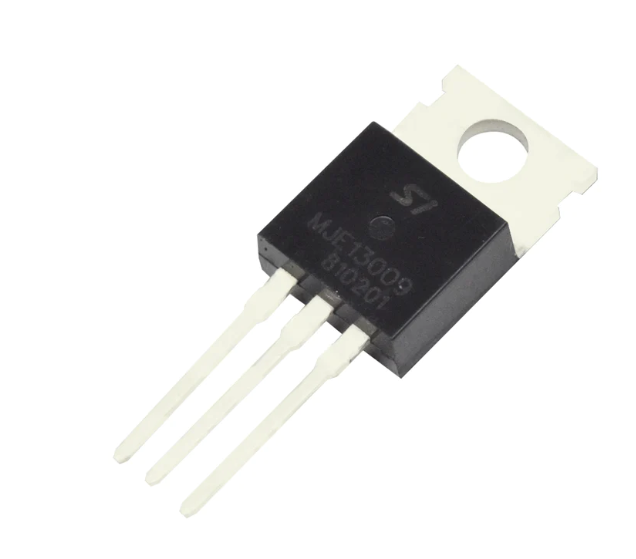
We are using Heat Sink because our power transistor gets very hot so we are using a heat sink to keep it cool. 1st we joint the heat sink in the transistor.

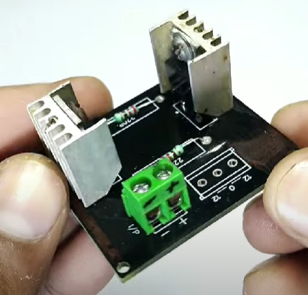
Let's go to assemble the PCB board

13009 Transistor

220R Resistor

2 pin terminal
After assemble we soldering all the component and our PCB look like
Here we are using a 12–0–12 (1 Amp ) transformer , {you can also use a 2,3 Amp transformer }. We will connect the three wires of the transformer to the PCB. On the PCB board it is mentioned where to add 12 Volts wire, and where to add center dept wire and solder it. Our transformer connection is done.
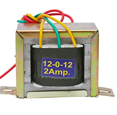
12–0–12 (1 Amp) transformer
Now we are using 12 volt female socket using input, so we connect female socket to the terminal point

Now we connect our transformer output in a bulb holder
Step 4: TESTING
Lets connect to the 12 volt output in the PCB and we will test with a multimeter, then we are using a 9 volt led bulb.

Step 5: APPLICATION
This circuit can be used in cars and other vehicles to charge small batteries also we are using at home when the current is shutdown.


![Tim's Mechanical Spider Leg [LU9685-20CU]](https://content.instructables.com/FFB/5R4I/LVKZ6G6R/FFB5R4ILVKZ6G6R.png?auto=webp&crop=1.2%3A1&frame=1&width=306)


