

Introduction: A Guide for Interfacing Seven Segment Displays With Arduino


Learn how to interface a Seven Segment Display with Arduino in this comprehensive guide. Seven segment displays are widely used for numeric display tasks in various electronic devices. This tutorial will walk you through the process of connecting and controlling a Seven Segment Display with an Arduino board.
Supplies
Components Needed:
- Seven Segment Display
- Arduino board
- Breadboard
- Jumper wires
- Current limiting resistors (e.g., 330 ohms)
- Computer with Arduino IDE installed.
Step 1: Understanding Seven Segment Display
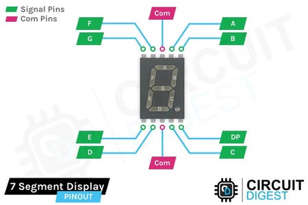
Before diving into interfacing a Seven Segment Display with Arduino, it's crucial to understand its basic principles. Seven segment displays are composed of seven individual LED segments arranged in a specific pattern to display numeric digits (0-9) and sometimes alphabets. These displays are categorized into two types: Common Cathode (CC) and Common Anode (CA). In a Common Cathode display, all cathodes of the LEDs are connected together and linked to the ground, while in a Common Anode display, all anodes are connected together and linked to the positive voltage supply. By controlling the activation of each LED segment, we can illuminate specific combinations to display desired numbers or characters.
Step 2: Connecting the Seven Segment Display to Arduino
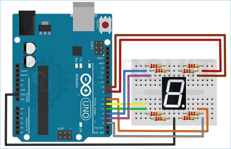
To begin interfacing the Seven Segment Display with Arduino, start by placing the display module on a breadboard with the decimal point facing downwards. Next, connect one of the common pins (either pin 3 or pin 8) of the display to the ground (GND) pin on the Arduino board. Then, wire the remaining pins of the display to digital pins D2 to D9 of the Arduino board through current limiting resistors. These resistors, such as 330 ohms, help regulate the current flowing through the LEDs, ensuring optimal performance and longevity. For visual guidance and clarity, refer to the circuit diagram provided with the tutorial.
Step 3: Writing Arduino Code
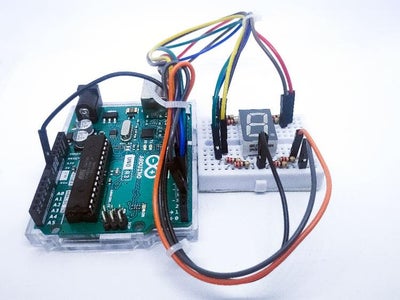
With the hardware connections in place, it's time to write the Arduino code to control the Seven Segment Display. Begin by installing the SevSeg library via the Arduino IDE's Library Manager. This library provides convenient functions for controlling Seven Segment Displays. Once the library is installed, create a new sketch in the Arduino IDE and copy the provided example code into it. The example code typically consists of instructions to count from 0 to 9 and reset back to 0, displaying the numbers sequentially on the Seven Segment Display. Additionally, the code may include functions to adjust brightness, customize display patterns, and more. After uploading the code to the Arduino board, observe the display as it cycles through the numbers, demonstrating successful interfacing between the Arduino and Seven Segment Display.
By following these steps and gaining a deeper understanding of Seven Segment Displays, you'll be equipped to incorporate them into your Arduino projects with confidence and creativity.


