

Introduction: AI Based Autonomous Swarm Robots for Warehouse Management

The proposed idea is to implement Autonomous Swarm Mobile Robots (ASMR) in Warehouse for package sorting & delivery. The system contains 3 stages. The first is to store materials in ASRS system to reduce space utilization. Conventional AMR uses multiple sensors to fuse data to localize and navigate it in warehouse. Second stage is to load/unload package to AMR and deliver to the buffer zone using information from camera. Third is to use ASMR for visual localisation and navigation.
OBJECTIVE:
- To develop 3 Stages of the proposed System
- To Construct and assemble 3-Axis Servo Gantry Skeleton system and use Delta PLC for controlling the operations of package sorting and transportation to the pick-up zone.
- To configure the SCARA Robot using Delta PLC to pick up the packages from the pick-up zone with vertical manipulation and load it into the C-AMR’s.(Centralized Autonomous Mobile Robot)
- To develop a Swarm Robot Delivery System for the C-AMRs based on ROS (Robot Operation System) for the desired warehouse layout.
- To use a centralized camera as the source of navigation for the C-AMR’s without embedding sensors to them with additional safety features.
- To develop control panel for the Servo Gantry System and SCARA Robot system.
- To develop novel control algorithm for the localization and navigation of C-AMR’s using Vision System.
- To develop an Industrial Internet of Things (IIoT) based GUI tool for visualization of the proposed system during runtime.
Supplies
Components Used
- ESP32 DevKitC 32E x4
- L298N Motor driver x8
- Servo Motor MG995 x4
- LM2596 STEP DOWN Voltage regulator x4
- LIPO Battery 11.1V x1
- DC Gearbox Motor x16
- Omni wheel x16
Step 1: Abstract
In the Intralogistics sector, logistics flow optimization, inventory management with pollution free environment (Green Manufacturing), energy conservation and timely delivery of the product to the customer is highly imperative in various Multinational companies around the world. Increasing inventories leads to increase the usage of Fuel Powered Forklift Vehicles for the transportation of materials and industry products. This increases pollution, fuel consumption, manual labours and cost. The usage of conveyor-based system and Decentralised AGV consumes more power, cost and complexity of computation process. The proposed idea is to design intra-logistics swarm robots with a centralized camera for navigation and pose estimation and completely creating a CARBON FREE logistics solution. The proposed system contains three stages of process. The first stage is to store the materials in the ASRS system to reduce the utilization of space. The conventional AMR uses multiple sensors to fuse sensor data to localize and navigate the AMR inside the warehouse. The Centralized monitoring and control of Swarm Robot System (C-AMR) eliminates all the sensor integrated inside the system to reduce the consumption of power and computation complexity. The customized algorithm is used for the localization and navigation of swarm robot using ArUCo marker via vision system mounted on the ceiling. Selective Compliance Assembly Robot Arm (SCARA) is used to load the material inside the Swarm Robot which delivers the material or package to the dispatch zones (Transportation area). This system increases productivity, ease of computation and reduces power consumption.
Step 2: Statistical Analysis of Intralogistics Growth
Intralogistics is expected to undergo a major growth around the globe over the next two decades. Quality in material handling and storage systems are involved in this major change. Since the intralogistics industry is essential for other industries like automotive, medical, agriculture and other major sectors. Over the past years, intralogistics has grown 10% each year. This number is expected to grow further and faster in upcoming years. The following graph shows the growth of intralogistics over different parts of the world. Among all south and east Asian countries are mostly involved in broadening the intralogistics market with an increase in market value of five times that of now. Pandemic has also played an important role in the surge of intralogistics.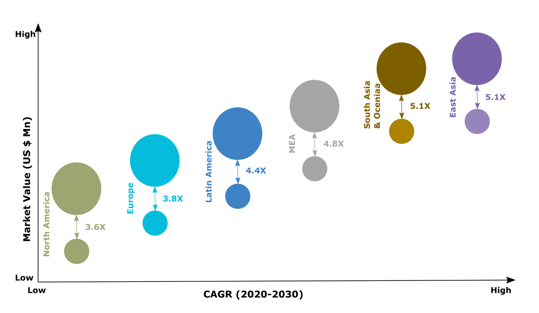
Step 3: Analysis of Fuel Consumption
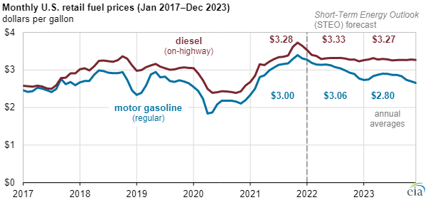
As rapid growth in intralogistics leads to conserve more energy, it is necessary to maintain low carbon footprint and switch to green manufacturing technologies. During one complete life cycle of a battery, a total amount of 10 to 19 tons can be liberated compared to diesel powered solutions. The evolutions of more powerful and robust mobile robots have made it possible to merge the electric drive into heavy-weight vehicles. The most powerful heavy-duty truck achieves a lifting capacity of up to 20 tons. The following statistical graph shows that an increase in transportation and fuel price is never expected to go down in upcoming years. Increase in fuel price can disrupt the market with huge losses. Fuel production has been declining over years drastically. With the current pace of fuel production and consumption, usage of fuel for commercial production and warehousing is not advisable.
- Analysis of Energy Consumption in Intralogistics: Uses of Automated Guided Vehicle (AGV) with integrated sensorsand other process inside the logistics takes a surplus amount of energy from order to dispatch the product to the customer. The below statistics chart shows the average consumption of energy in various warehouses. Among all the tasks, transportation inside the warehouse consumes the more energy. On average, mobile units are the one which consumes energy exponentially. The below graph shows the energy consumption of redundant sensors. Even though the numbers are small in comparison, when calculating the average energy consumption over a year each unit consumes 832.2 kW/h by considering 20 hours per day. In case of a medium scale warehouse, it is expected to use at least 10 mobile units for efficient sortation , which totals into 8322.2 kW/h for a single warehouse.
- Problem Statement: As intra logistics is growing exponentially, the need for automation has become a andatory prerequisite for all the industries who are dealing with large inventories. Various methodologies have been deployed to in rease the potential of warehouses through automation. These include forklifts with manua. l labours, conveyor-based storage system, autonomous guided vehicles. Usage of manual forklifts can consume more fuel during transportation inside the warehouse and emits high carbon to the industry environment. It limits the inculcating automation with the usage of manual laborers. Since this method uses fuel powered vehicles for material handling inside the warehouse environment, it is necessary for the industry to deploy alternative and effective methods for creating LOW-CARBON environment inside the manufacturing and warehouse sections. Usage of fuel declines the emergence of green manufacturing and sustainable energy management. Conveyor based warehouse systems and AGV are also used in warehouse management. Though this system has complete autonomy, deployment of these solutions requires downtime during its commission period. In addition, these systems are not agile enough to adapt to new spaces after deployment. New infrastructure and downtime of a warehouse is not an option to the current intra-logistics industry anymore. To bring the best of both solutions (conveyor based and AGV’s), Autonomous mobile robots have gained traction in intra-logistics due to its fast deployment and flexibility to new workspace. This robot can increase the throughput in existing industrial environments without any modification. This robot can increase the throughput in existing industrial environments without any modification. Despite its upper hand over other solutions, this solution too has its own caveats to mention. As multiple robots are used to increase potency of the warehouse, the same sensors and computing units are used in each agent (AMR unit) causing redundancy. These surplus sensors cause a surge in multiple factors like energy consumption, cost, complexity in computation and time lag of the robot. Further these robots are not affordable to the medium and small-scale logistics division due to increase in silicon price and other electronic items.
Step 4: Experimental Setup
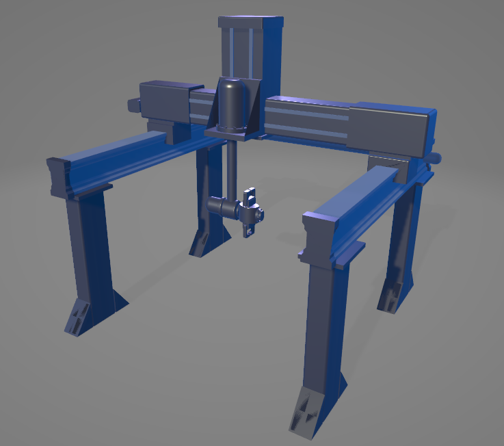
1. 3-Axis Gantry System
3-axis Gantry System comprises of three ASDA-A2 Servo amplifier & 400W
servomotor which provides motion along x, y and z axis. The AS228T PLC provides high speed pulse output from Y0 and Y1 for the position control of servomotor. The linear actuator displaces 5mm distance per revolution of ball screw rod. The linear rail provides support and smooth motion along all the three axes. The pneumatics gripper is used to hold the object for pick and place operation.
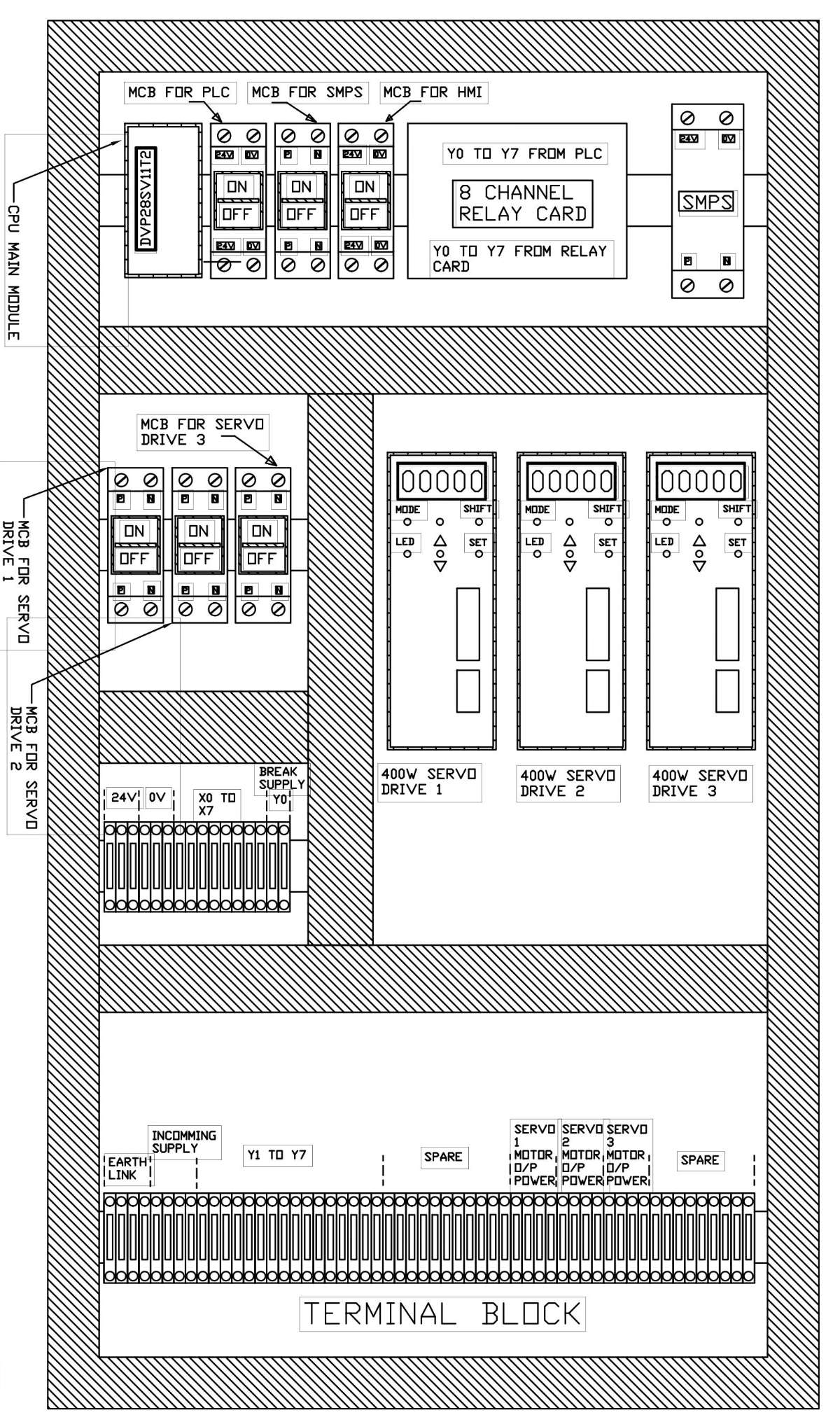
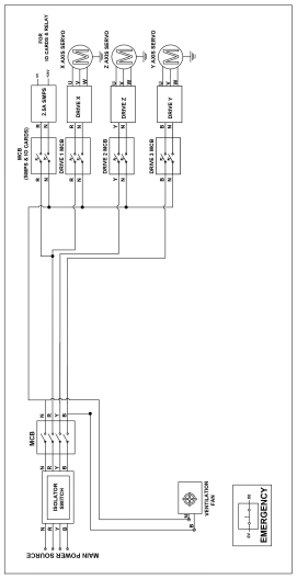
Control panel layout for gantry system:
control panel wiring for gantry system:
SCARA ROBOT SYSTEM:
CONTROL PANEL LAYOUT FOR SCARA robot:
SWARM ROBOTIC Delivery system:
Each of our individual C-AMR of the Swarm Robot Delivery System comprises of a NODE-MCU as its Central Processing unit. This is an Omni-wheel drive which has its advantages of not having to turn in order to change to direction of movement which would be a huge advantage inside any intralogistics warehouse. Two L298N drivers are used to control the four DC motors with each one controlling two for each axis. A mini-Servo is used to drop the packages into the buffer zones in the appropriate direction.
- Warehouse Layout:
- Robot pose estimation using RVIZ tool from vision system
Methodology:
The above conceptual diagrams illustrate the comprehensive working principle of the proposed system. The proposed system consists of four units of process, namely
Networking and processing unit
Gantry unit
Loading unit
Mobile unit
The sequence and procedure of these units are described in detail below.
Step 5: Networking and Processing Unit:
This unit is the foundation in the workflow of the whole system. This unit includes user application, admin panel, processing server. All units in this system are interconnected with each other using ethernet and WIFI. This system also helps in communication of non-networked devices by bridging them with other modes of communication like CAN. This helps in creating synchronous workflow within the warehouse and reducing the intervention of manual laborers. First off, the unit starts when a customer orders a product through the provided application. The information of the product and other necessary information are received over HTTPs to the processing server. The server processes the information and finds the storage location of the ordered product. Then the server, passes the identified information to gantry unit. The gantry unit provides continuous stream of feedback and a result when the action is completed. This information is stored in SQL server, for visualization. In the admin panel, the progress of each task is organized and displayed to the warehouse management. Additionally, this unit works as a warning system in case of a failure in the other systems.
Step 6: Gantry Unit
The Gantry unit is Delta’s ASDA-A2 Series three-axis AC Servo System which is used for multi-axis motion control application. When a signal is received from the server representing the location of the required package through CAN bus, the PLC actuates the servos using the individual servo’s drive with the appropriate pulses required to reach the destination of the required package. The pulses required to follow the paths are pre-programmed and uploaded into the PLC. Once it has reached its destination, the gripper is actuated to grab the package. Then the Package is moved and dropped in the area for Loading unit. After completion of the process the Gantry System sends the feedback to the server indicating the availability of packages for the Loading unit.
Step 7: Loading Unit
The loading unit consist of Delta’s SCARA DRS40L Series robot which has 4 axes, sensor-less, high speed robot. In the loading unit, SCARA Robot is used to load the package to the C-AMR. The Gantry takes the packages from the rack and places it in the picking zone. Then SCARA robot picks the packages and places them into the C-AMR. If any packages are available in the picking zone, SCARA receives an input from ROS Server. The SCARA picks the package from the picking zone and checks for the availability of C-AMRs in the loading area. SCARA Robot loads the package into the C-AMR whose destination is closer from loading area. If any of the C-AMRs are not available, the SCARA waits for a C-AMR to arrive in the loading area. When the loading unit completes the process, feedback is sent to the central server.
Step 8: Logistic Unit
This unit addresses the way of delivering the package to its station. To begin with, localisation of the C-AMR’s is done using an array of camera arranged, such that the total surface of warehouse is monitored every time. These cameras are used to identify the position of a C-AMR with respect to itself. Then transformation of robot with respect to the world is calculated using homogeneous transformation matrix. Once the robot is localized in workspace, it is easy to navigate around the warehouse. The navigation starts when feedback from SCARA robot is sent to the central server. Then the server searches the optimal path required from a HashMap of predefined paths stored in server. When no paths are found, a A* planner plans a new path from the robot’s current position to its destination and adds the generated path to the hashmap. This is done to reduce computing complexity and repeated calculation of paths and trajectories. The below image depicts the path generated for the test warehouse layout.
Once the path is found, the server calculates required velocity using a proportional algorithm and sends the generated velocity to the robots through WIFI. The C-AMR receives the signal with its inbuilt WIFI controller. This controller is a 32-bit microcontroller with dual core processor powering the compute unit of each C-AMR. A second level of PID controller is implemented in each C-AMR for accuracy and precision. When a velocity command is received, the controller provides an appropriate PWM according to the inverse kinematics of holonomic C-AMR. The provided PWM is applied to each pin in which motors are connected. The mobility of each C-AMR is monitored when a command velocity is sent. When a C-AMR is collided in a place, recovery behaviour is started. This recovery behaviour tries to move the bot away from its current state. The following image portrays the recovery behaviour of a C-AMR it is collided near buffer zone.
Recovery behaviour calculates the shortest distance to recover the robot from its obstacle. This provides a smooth operation even during an unavoidable accident. In addition to this, collision detection between each robot is also monitored to avoid the above-mentioned accidents. A suitable polygon is drawn virtually to cover area of the robot. This virtual polygon is used to detect collision between each C-AMR. When a collision is detected, angle between the robots is calculated and aC-AMR is stopped according to the angle. This method avoids deadlocks in the given workspace with the least amount of calculation. Furthermore, potential deadlocks are identified from the paths and C-AMRs are stopped beforehand.
The above-mentioned methods aid the C-AMRs in mobility of the robot from the start to end of the destination. Once the C-AMR reaches the destination, it drops the package and sends the status to the ROS server. The server then identifies the nearest induct station and calculates the destination and publishes the velocity to the C-AMR. When the C-AMR reaches nearer to the induct zone, it checks the occupancy of the induct zone. If the induct occupancy is false, then C-AMR sets occupancy to true and docks it inside the induct zone. While the induct occupancy stays true, other C-AMRs reaching the same index remains in the waiting zone. The induct occupancy is again set to false when the robot leaves the induct station. Thus, this complete unit wraps the complete cycle of the workflow by delivering the previously loaded package to the desired location.
Step 9: Conclusion
As a result of implementing this solution, a huge amount of energy may be conserved by reducing redundant sensors as well as elimination of fuel powered intralogistics vehicles. In addition to this, carbon emission is drastically reduced due to the usage of electrical motors and electrical components in each C-AMRs. Each warehouse is able to increase the efficiency without any other negative environmental impact. Also, these warehouses can operate without any breaks leading to faster intralogistics and enables complete tracking in GUI. We hope this would be a great life saver to current intralogistics industry.
GUI:
RQT GRAPH:
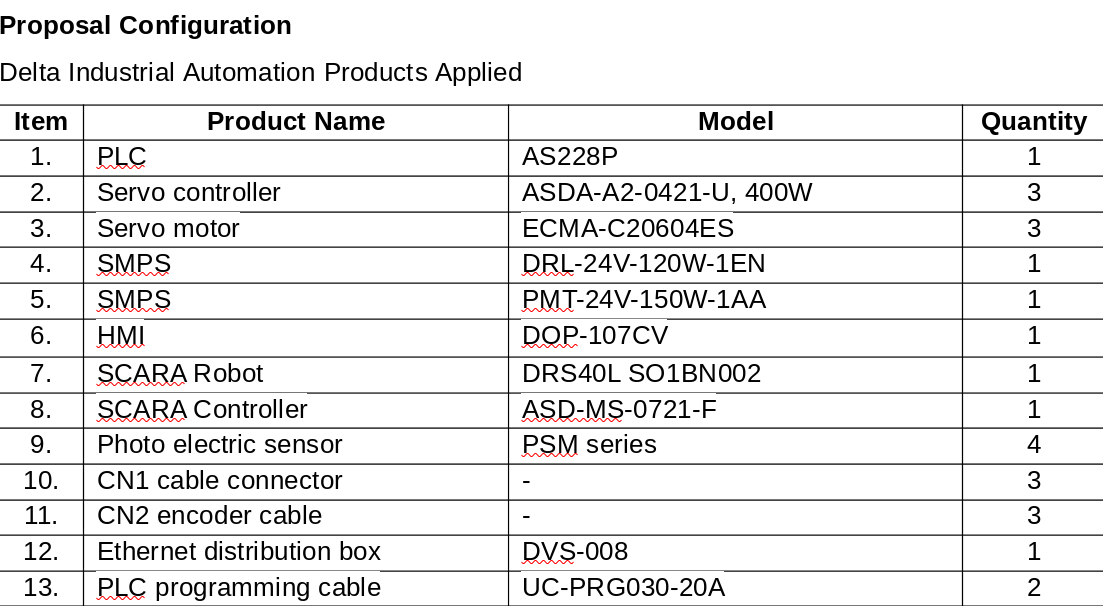
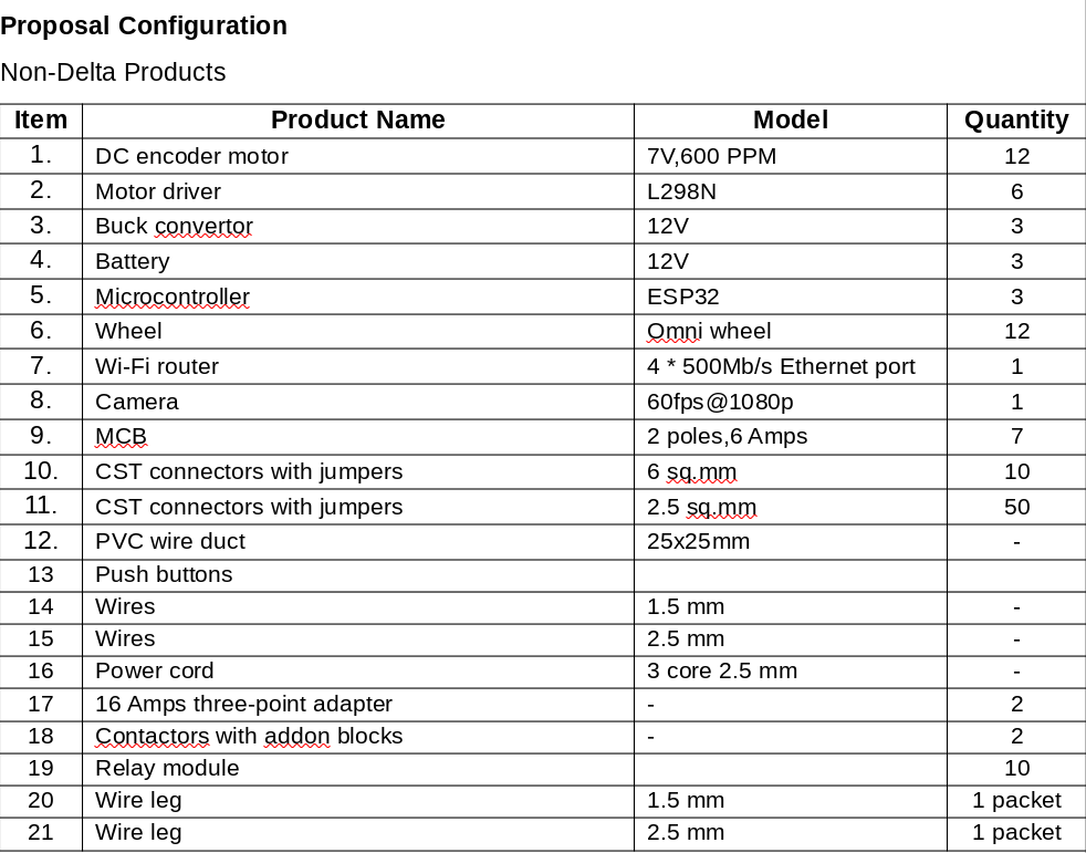
PROPOSAL STRUCTURE:
Step 10: Complete Setup Video
Step 11: Swarm Robots

Participated in the
Anything Goes Contest


![Tim's Mechanical Spider Leg [LU9685-20CU]](https://content.instructables.com/FFB/5R4I/LVKZ6G6R/FFB5R4ILVKZ6G6R.png?auto=webp&crop=1.2%3A1&frame=1&width=306)


