

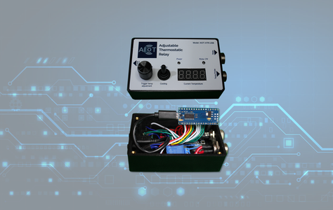
Introduction: Adjustable Thermostatic Relay (using Arduino Nano)
This is a fun project to learn the Arduino Nano and how to build your own Adjustable Temperature Monitoring and Control Device.
The way the adjustable thermostat works is that external DS18B20 waterproof sensor feeds the temperature in real-time to the microcontroller and then to the LED display. You can use either a short press or a long press of the rotary encoder push button shaft to set the low temperature limit (short press) or the high temperature limit (long press). Once in either of the modes, you rotate the encoder in the clockwise or counterclockwise direction to increase or decrease the temperature value. If the knob is not turned for more than 3 seconds, it exits the function and resumes displaying the real-time temperature. If the real-time temperature is either bellow or above your preset limits, the relay closes and whatever you have connected to the relay (heather, fan, etc..) is turned on.
These instructions show you how to build the device, all the theory behind how the unit works as well as a great crash course on how to use the Arduino Nano can be found here: Arduino Nano Thermostatic Relay Project
Supplies
Arduino Nano Board | Arduino Official Store
DS18B20 Waterproof Temperature Sensor | Amazon.com
4-Digit LED TM1637 Display Module | Amazon.com
Rotary Encoder Module | Amazon.com
SPST Mini ON/Off Toggle Switch | Amazon.com
5V One Channel Relay Module | Amazon.com
Green 5mm LED Pack (incl.Resistors) | Amazon.com
Red & Green LED's Pack (Small 3mm LED's) | Amazon.com
Assorted Resistors Kit | Amazon.com
Panel Mount Extension Mini B USB Cable - for Nano models with Mini USB | Adafruit.com
OR
Panel Mount Extension Micro B USB Cable - for Nano models with Micro USB | Adafruit.com
GX12 Male Female 12 mm 3 Pin Connectors | Amazon.com
GX16 Male Female 16mm 2 Pin Connectors | Amazon.com
Stranded Wire Kit 22 Gauge 6 Colors 26.2feet Each | Amazon.com
Electrical Wire 14 AWG 14 Gauge Silicone Wire | Amazon.com
5V 2A Mini USB Power Supply Wall Charger | Amazon.com
OR
5V 2A Micro USB Power Supply Wall Charger | Amazon.com
M3 Threaded Insert Knurled Brass Nuts Female (for securing cover) | Amazon.com
M3 x 10mm Alloy Steel Hex Socket Head Cap Screws (for securing cover) | Amazon.com
M2 Threaded Insert Knurled Brass Nuts Female (for securing TM1637 display) | Amazon.com
M2 x 4mm Phillips Screw Fastener Black (for securing TM1637 display) | Amazon.com
Optional if not using 3D printer for Project Case:
Fielect Project Box (3.94" x 2.36" x 0.98") | Amazon.com
Step 1: Project Case Choice


Before you start building, you’ll need to decide whether you are going to use a manufactured project case such as the one listed in the parts list or use a 3D printer and print your own using the files included in the resources folder of the online course.
Using the 3D printed case will save you time as you will not need to drill or cut any holes.
However, if you don’t have access to a 3D printer, you can use the manufactured case listed in the parts list (or something similar) and use the printable templates we’ve included to help you in cutting and drilling the holes for the various components. If you do decide to use these templates, keep in mind they were designed specifically for the case listed in the parts list (Fielect ABS Plastic Project Box 3.94" x 2.36" x 0.98”) and when printing the template, make sure to print them at 100% size. Also, double check before making any cuts.
You’ll find that drilling the round holes is the easy part, cutting the square hole for the 4-digit LED display is the hard part. Here, we strongly suggest you first cut/drill well within the lines of your square hole, and then use a small flat file to finish. This will take some time, but you’ll be happy with the results.
If you decide to make your own 3D print of the case, use both the file named ATR-USB-Case.stl and the file named ATR-USB-Cover.stl. Simply take these files to a 3D printer service provider or print them yourself if you own a 3D printer.

Step 2: Affixing the Cover Label


Before you can begin mounting your components to the case, you will need to print and affix the cover label to your project case. We recommend you use high quality glossy sticker paper as it will make it much easier to affix to your project case. We’ve had very good results with this Glossy Silver paper. Use the appropriate file (see below) to print the cover label using 100% for size and the highest resolution available. Once printed, cut the label as per the instructions on the label and shown in the first image above.
Peel and carefully remove the protective layer from your sticker paper and carefully align the cover label on the project case. We recommend taking your time here and first aligning the left side and aligning your label before gradually setting it on the surface from left to right as per the second image above.
Once properly installed, use an X-ACTO knife to carefully cut the holes for all the components. Again, take your time to achieve the best results.
After cutting all the holes for your components, we highly recommend that you spray a thin coat of clear lacquer directly on the label. This will help protect and preserve it.

Step 3: 3. Pre-wiring the Components


Prior to installing the components inside the project case, we will pre-wire them. This will make it much easier to manipulate the components as we solder the wires to them. We’ll be using 22 AWG gauge for most of the components except for the GX-16 male relay connector where we will use 14 AWG gauge wires.
Let’s start with the Rotary Encoder, initially cut each wire to four-inch lengths, they will be cut shorter as required in later steps. So cut (5) 4-inch 22 AWG gauge wires. If possible, use 2 blacks, 1 white, 1 green and 1 yellow as this will make it easier to connect later. Also, pre-solder the ends of each wire to make the next steps easier.
After soldering your wires, we strongly suggest using some protective shrink tubing to avoid any of the wires from shorting as they are in very close proximity of each other.
Refer to second image above and solder the green wire to the DT (A) pin, two black wires to both grounds, the white wire to the CLK (B) pin, and finally the yellow wire to the switch pin.
Next, we’ll pre-wire the TM1637 LED display. So cut (4) more 4-inch 22 AWG wires, 1 black for ground, 1 red for 5V, 1 white for CLK and 1 green for DIO. Here, make sure you solder the wires, so they are coming out of the back right side of the TM1637 as illustrated in the third image. When we later install the LED display in the project case, the four wires will be located towards the middle of the case.
The next part we’ll pre-wire is the Relay Module. Once again, cut (3) more 4-inch 22 AWG wires, 1 black, 1 red and 1 white. Here, make sure you solder the wires, so they are coming out of the top component side of the relay as illustrated in the fourth image. This is important as the relay will be seated inside the flat portion of the case when we later install it. Make sure to also use protective shrink tubing if required.
The next item we’ll pre-wire is the mode selection toggle switch. Cut (2) 4-inch 22 AWG wires, 1 black and 1 yellow. If your toggle switch has three connectors, solder the black wire to the center connector and the yellow wire to either of the other two connectors. If your toggle switch has only two connectors, don’t worry about which wire goes were. Make sure to also install some protective shrink tubing.
We’ll now wire the two males ends of our GX12 and GX16 connectors. Cut (3) 4-inch 22 AWG wires, 1 red, 1 black and 1 yellow. Here we have soldered our red wire to pin 1, our black wire to pin 2 and finally our yellow wire to pin 3. Make sure to note the pins you use, as this will be important later when we wire our female connector to the temperature sensor. Also make sure to add some protective shrink tubing on each of the wires.
For the GX-16, we recommend that you use a larger gauge wire such as 14 AWG. So, cut (2) 2-inch 14 AWG wires. Depending on the connector you’re using, you may need to remove a few strands at the end of your wires to obtain a better fit. When you’re happy with the way the wires and connector terminals fit, pre-soldering both the connector and wire ends will make it easier to solder these larger wires. You’ll also need to add some protective shrink tubing on these wires as well.
The last items we need to pre-wire are the two LED. First cut (4) 4-inch 22AWG wires, 2 reds and 2 blacks. You’ll also need (2) 470 ohms resistors for this step. First cut both sides of your resistor to ¼ inch lengths. Also cut the leads of the positive anode sides of your LED’ to ¼ inch. Solder one side of your resistors to the red wires, then solder the other side of your resistors to the anode positive side of your LED’s. Next, cut the negative cathode side of your LED’s leads to ¼ inch. Then solder the black wires to the LED negative cathodes. Finally, slip shrink tubing over both wires making sure to cover the entire resistor on the red wire as shown in last image above. Once you have fully assembled your LED, we highly recommend you test them by applying 5 volts DC to confirm they are working correctly as we will be epoxying them onto the project case in a later step.
Step 4: Installing Components in the Project Case


We’ll now start installing the components inside the project case. You’ll need some two-side mounting sticky tape to hold some of the components in place. You will also need some 5-minutes epoxy to ensure that some of the components, such as the LED’s remain fixed in place.
To install the TM1637 LED display, first loosely insert the 4 smaller M2 threaded inserts into the four posts holding the display inside the case (pay attention to the orientation as shown in the first image). With the tip of your hot soldering iron perpendicularly position in the hole of the nut, apply slight downwards pressure until each of the nuts are flush inside the holes as illustrated in the second image. The rectangular hole for the display may need to be slightly filed, so check the fit and if needed, lightly file the opening. Once satisfied with the fit, insert the display inside the project case with the wires toward the middle of the case as illustrated in the third image, and secure with (4) M2 x 4mm Phillips screws.
The next two components we’ll install are the toggle switch and the rotary encoder. So, remove the securing nut from the shaft and install them onto the project case. Secure them with the nut and make sure to use the round washer when tightening and be careful not to scratch the surface of your label when tightening.
Next install the GX12 male temperature connector and secure it by first passing the washer and then the nut over the three wires. When tightening the nut, make sur that the alignment notch inside the connector is facing toward the front side of your project case as per the fourth image.
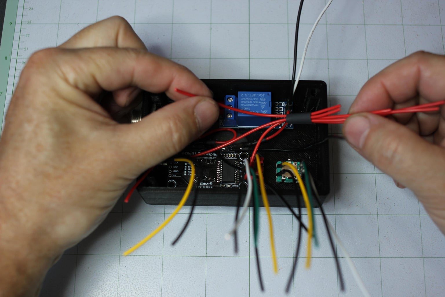
We will now position the GX16 male connector inside the project case, temporarily securing it with the washer and nut. Here again, make sur that the alignment notch inside the connector is facing toward the front side of your project case. Now enter the Relay Module into the project case holding it in place approximately ½ an inch from the left side (when looking toward the inside) of the project case. Using either your fingers or long nose pliers, bend the two 14 AWG wires so that they are aligned with both the normally open and common relay connectors as shown in the fifth image.
Once correctly aligned, remove both the GX16 and relay module from the project case. Carefully remove about ¼ inch of insulation on each of the 14 AWG wires. Now untighten the screws on the relay module and test fit the wire to see if you can easily insert them inside the relay’s connectors. Depending on the model of your relay module, you may need to insert a very small flat screwdriver and delicately pry open the openings of the connector holes to allow for a bigger wire. Also, if needed, you may also remove a few wire strands from each wire until you get a nice fit inside both connectors. Next, cut a small square of two side mounting sticky tape equal or smaller than the bottom surface of the relay module. Peel-off and install the mounting tape on the bottom side of the relay module, but do not remove the protective film on the exposed side of the tape yet. Re-install the GX16 male connector to the project case and slip the both the washer and the nut over the two wires. Now position the relay module inside the case and first insert and tighten both wires to the Normal Open and Common connectors of the relay module. Next, tighten the GX16 nut and once everything is secure, peel the protective film from the back of the relay module and carefully position it in the project case as shown in the sixth image.
The last two components we will install are the two LED’s. The green LED will be used for the “Relay ON” and the red LED will be used for the “Power”. Prior to installing, gently bend the two wires at the base of the LED 90 degrees (see seventh image above). Next, insert both LEDs in the correct positions with the wires positioned approximately as shown in the second to last image. Finally, mix a small quantity of “5 minutes” epoxy glue and carefully drop a few beads over the LEDs and the first ½ inch of the wires as shown in the last image. Important: Make sure your project case is perfectly horizontal or the glue will run off.
Let the epoxy set completely before moving to the next steps.
Step 5: Wiring Our Negative and Positive Wires


We’ll now wire all the positive and negative wires together. Before we do this, cut (2) more 4-inch 22AWG wires, 1 red and 1 black. Starting with the positive wires, gather each of the following wires: 1- the red wire from the relay, 2- the red wire from the GX12 temperature sensor male connector, 3- the red wire from the TM1637 LED display, 4- the red wire from the RED LED and finally, 5- the 4-inch red wire we just cut.
Make sure you do not include the red wire from the green LED as this will be connected later to the microcontroller.
Prior to twisting all these wires together, cut a short ½ inch shrink tube large enough to fit all the wires and slip it over the 5 wires. Using the shrink tube, carefully adjust the wires so that the unconnected cut wire is the same length as the shortest wire, and they are all oriented and positioned as shown in the first image. Using wire cutters, cut the wires approximately ½ inch from the shrink tube as shown in the second image.
Next, remove the ½ inch shrink tube and remove ½ inch of insulation on each of the 5 wires. Re-install the shrink tube over the 5 wires, and carefully twist all the wires using your fingers. Next, solder the 5 wires and cover them with a protective shrink tube as shown in the third image.
Next, we are ready to repeat the same process, but this time for the negative wires. So, gather each of the following wires: 1- the black wire from the relay, 2- the black wire from the green LED, 3- the black wire from the red LED, 4 & 5- the two black wires from the rotary encoder, 6- the black wire from the toggle switch, 7- the black wire from the TM1637 LED display, 8- the black wire from the GX12 temperature sensor male connector, and finally 9- the 4-inch black wire we cut in the first step. That’s 9 wires in total, so make sure you have them all. Once again, prior to twisting all these wires together, cut a short ½ inch shrink tube large enough to fit all the wires and slip it over the 9 wires. And now simply repeat the same steps illustrated for the red wires. Make sure the terminal for the red wires is pushed to the bottom of the project case and that the terminal for the black wires is positioned towards the top as shown in the fourth image.
Next, we will secure the USB cable to the project case. Insert the USB cable between the red wires and the black wire from the relay. Once in position, you should be able to align the connector with the hole on the side of the project case. Refer to the fifth image to see how your cable should be correctly positioned.
Finally, secure the USB cable to the project case using two M3 x 10 mm hex screws as shown in the last image. This now completes the first part of the components wiring. In the next step, we will solder the remaining wires to our microcontroller.
Step 6: Wiring the Microcontroller


We will now start soldering each of the remaining wires to our microcontroller. Let’s first start with the positive and negative wires coming from the terminal wire bundles. Remove about 1/8 inch of insulation on each wire and solder them to the GRD and 5V pin. Make sure to enter the wires on the top side of the microcontroller as illustrated in the first image. Next, run the three wires from the Rotary Encoder and solder them to the microcontroller as follows: the CLK or (B) white wire to pin 2, the DT or (A) green wire to pin 3, and the switch yellow wire to pin 4 as per the second image.
The next wires we will connect are for the toggle switch and the TM1637 LED display. So, connect the yellow wire from the toggle switch to pin 5, the white CLK wire from the TM1637 LED display to pin 6 and finally the green DT wire to pin 7. If some of your wires seem a little long, cut between ¼ to ½ inch off prior to soldering them so they all fit neatly as shown in the third image.
Let’s now wire our last three wires to the microcontroller starting with the yellow data wire from the GX12 temperature sensor male connector to pin 8. Finally, connect the input white wire from the relay module to pin 9 and the remaining red wire from the green LED to pin 10 as shown in the last image.
Step 7: Installing Female Connector to the Sensor


In the section, we’ll guide you through the process of installing the female GX12 connector to the DS18B20 waterproof temperature sensor. We will also install the required 4.7 K Ohms resistor inside the connector. First cut the 3 wires to a length of ½ inch from the wire sleeve. Then remove 1/8 inch of insulator from each wire. Also cut a 1-inch protective shrink tube which is just large enough to fit over the sleeve. Enter the female connector cover and the shrink tube in the same order as shown in the first image.
We will be integrating a 4.7 K Ohms resistor inside our connector. We’ll need to cut ¼ inch on one side and ½ inch on the other side of the resistor as shown in the second image. As we’ll be soldering small wires on a very small connector, it will be important to pre-solder both the connector as well as the wires and the resistor as shown in the third image, as this will make the next steps much easier to accomplish. Locate pin 1 of your connector and first solder the short end of the resistor as shown in the fourth image.
Next, bend the top of the resistor so that its other end is in contact with pin 3 and solder it in place as shown in the fifth image. We will now solder the three wires to the connector. With the connector cover and shrink tube installed over the wire, first solder the red wire to pin 1 along the already soldered resistor. Next, solder the negative black (or blue) wire to pin 2 and finally the yellow data wire to pin 3 along with the already soldered resistor. Refer to the sixth image for an example of what your soldered connector will look like. Next, slip the shrink tube all the way over the resistor and soldered wire and apply heat to shrink tube so that its nice and tight over the wire and the connector’s exposed solder as shown in image 7. Finally, carefully screw the connector to the cover making sure that the wire turns loosely inside and then tighten both screws at the neck of the connector as shown in the last image.
Step 8: Final Assembly


The two last steps we must complete are to properly position and connect the USB cable to the microcontroller as well as insert the 4 female M3 threaded & knurled brass insert nuts. Let’s first install the brass nuts by loosely inserting them in each of the four holes (pay attention to the orientation as shown in te first image). With the tip of your hot soldering iron perpendicularly position in the hole of the nut, apply slight downwards pressure until each of the nuts are flush inside the holes as illustrated in the second image.
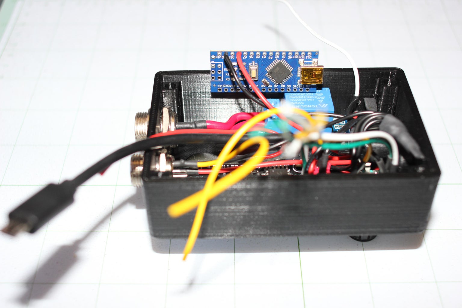
We’ll now connect our USB cable to the microprocessor. With one hand, move the microcontroller out of the way, make loop with the USB cable so that it is positioned as shown in the third image. While holding the USB cable in place, position the microcontroller inside the project case as shown in the fourth image and connected to the USB cable. Be mindful of your microcontroller being too close to the GX12 connector as it could create a short. If needed, you can put a small piece of electrical tape under the microcontroller to prevent this. Use the project case cover to hold everything in place, and when closing the cover, make sure the wires on the microcontroller are not pressing down on the Nano’s reset button.
Congratulations, you have now completed your very own portable Adjustable Thermostatic Relay.


![Tim's Mechanical Spider Leg [LU9685-20CU]](https://content.instructables.com/FFB/5R4I/LVKZ6G6R/FFB5R4ILVKZ6G6R.png?auto=webp&crop=1.2%3A1&frame=1&width=306)


