

Introduction: Arduino Robotic Arm


I have bought 2 joysticks from ebay and tried to think what can I do. Then I came up with idea to make a small robot arm. What I needed was:
1x Arduino Nano
3x MG996R servos (I used one Futaba, because I had only two MG996R and it was not necessary to have much torque for turning)
1x Micro servo
2x Two axis joysticks
1x 6V voltage regulator
1x Battery
Other items: double sided PCB covered with photoresist, diode, capacitor, switch, socket for Arduino Nano, strip cable with connectors, PCB stands, screws, bike spokes for pushrods, linkage stoppers.
Step 1: Sketching and Modelling


I borrowed the frame from backhoe and made some sketches. Then using AutoCAD I made a 3D model. It was one of the longest step during production. I attach AutoCAD and .stl files if you want to see or take some ideas. Also I drew an outline for control joystick.


Step 2: Production


As you probably saw, the 3D parts are made of rectangle pipes. The reason of this is that I wanted to make the robot of aluminium pipes, but when I started, I realised that it is too big challenge. The bending places breaks, so it has to be hot, but I don't have equipment for that, so I jumped to 3D printing technology.
I brought 3D model to local company and it printed the parts for $25. That wasn't the best quality, but acceptable for this robot.
Step 3: Assembly

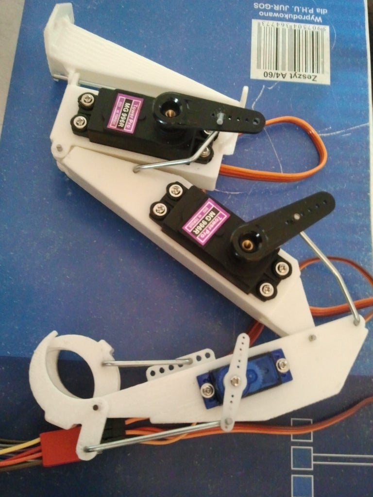
The best part of production was assembly. All I needed to do was to insert servos, make hinges of spokes, bend and connect spokes for pushrods.
Step 4: Programming and PCB Production


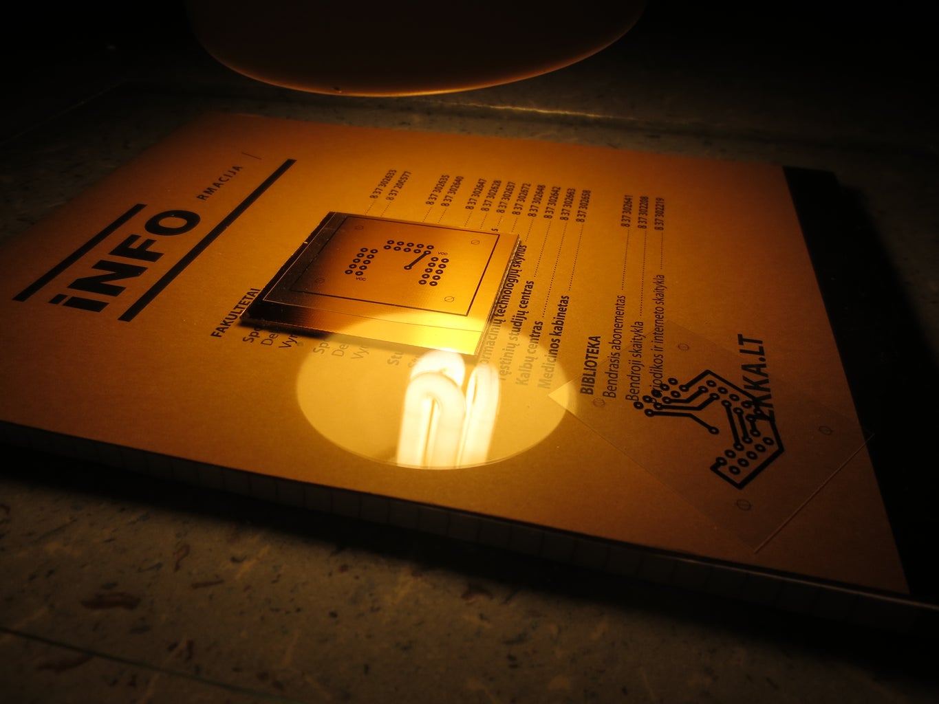

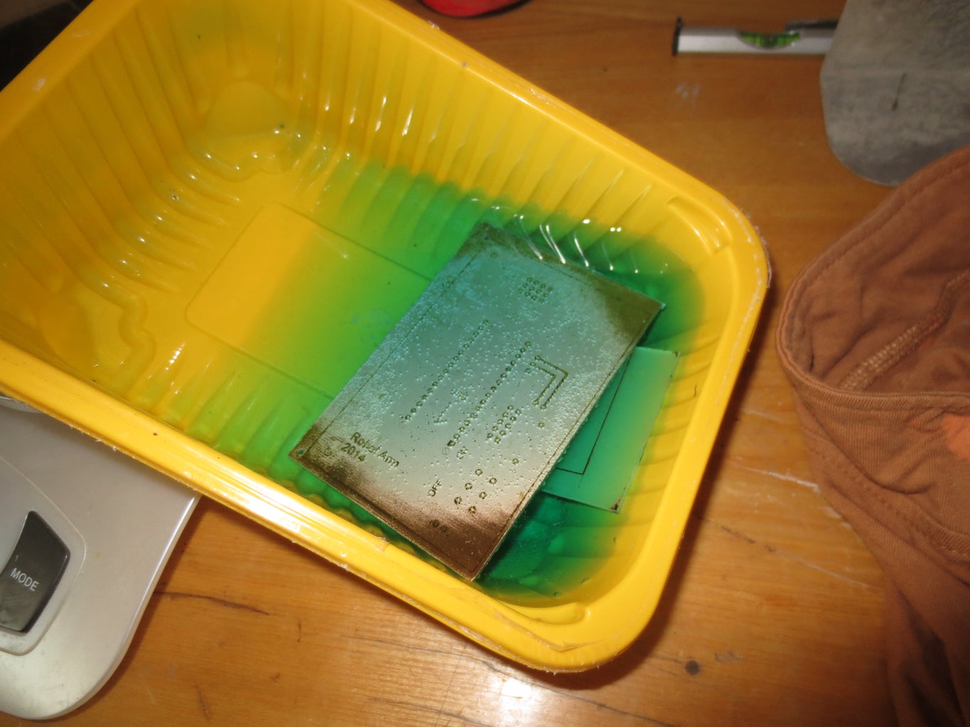
First I have made testing circuit on breadboard and wrote a program with Arduino software. I attach the code here. Then I drew tested circuit with Eagle software and printed it on transparent paper, which you can buy in almost any office. After that I peeled of the cover film from PCB, put on circuit scheme and using energy saving lamp exposured the board. I have made 2 boards, one for robot and one for control joystick. Following step was to clean left photoresistor in alkali bath and after that etching. After etching I drilled the holes and PCBs were ready to solder.
Attachments
Step 5: Base and Joystick Assembly, Soldering


I used plywood to make base and joystick. When PCBs were soldered, I attached them to plywood. And here it comes two errors of designing PCB:
- Lower holes of control joystick PCB are partly covered by connector sockets, so it's not possible to screw the board through them;
- Connector socket, which goes to robot is placed incorrectly. I messed up with pins, so I had to solder it upside down.
Last two things was to connect all wires and calibrate the movements.
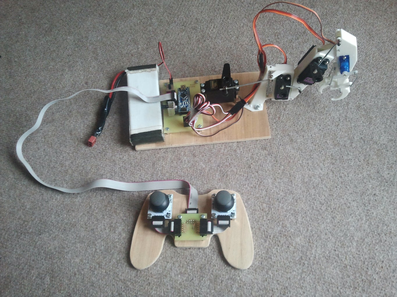
And that's it, here is finished Robot Arm.
Step 6: Presentation
In this video you can go through again all these steps and check how the Robot Arm works. By the way, control is based on the ISO pattern.
If you like my project, please VOTE. Thank you for your interest!

Participated in the
First Time Author Challenge

Participated in the
Microcontroller Contest


![Tim's Mechanical Spider Leg [LU9685-20CU]](https://content.instructables.com/FFB/5R4I/LVKZ6G6R/FFB5R4ILVKZ6G6R.png?auto=webp&crop=1.2%3A1&frame=1&width=306)


