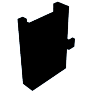
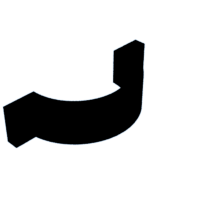
Introduction: Bicycle Phone Holder
This accessory was created for a bicycle in order to have a place for a phone to be secured during biking. The tutorial was created using a 3D modeling software with a phone that had been previously designed to the specifications of an Iphone, but the dimensions can be adjusted to fit any bike/phone dimensions.
Supplies
-3D printer with filament
-1/8"x3/4" (#8) bolts with 1/8" nuts
Step 1: Create the Outline of the Holder
To begin, the basic structure of the holder was designed with custom measurements to the bike bar and phone width/depth input as shown in the photo. For these measurements, the inner radius of the surface (orange box) was equal to a sample bike's measured radius of 2 inches, and the green/pink measurements are equal to the depth/width of my personal phone. For the width/depth 1/2" was added to each in order to provide additional space for outer walls. These measurements can be adjusted and changed accordingly to specific bike/phone measurements. The unspecified dimensions are arbitrary and were determined in order to create a compact, stable structure.
Step 2: Extruding Main Structure
Next, the support and the phone encasement are extruded to separate lengths. The first extrusion is arbitrary and was extruded to 3/4" in order to provide necessary support. The secondary extrusion, however, was adjusted based on the dimensions of a personal phone and was extruded symmetrically to a length of 7 inches, so the phone could fit fully inside with the support in the middle.
Step 3: Forming First Open Face
Next, the first open face was formed. As the measurement of the overall width should be 1/2" less than the width of the phone, providing a 1/2" wall on either side allows for the phone to fit inside without falling out, yet the screen will still be visible (if directions, etc. want to be accessed during the trip). This surface was then removed to the total depth-1/4" to fit the phone depth as well.
Step 4: Forming the Phone Cavity
Next, the cavity is formed by sketching a rectangle that provides 1/4" wall completely surrounding the cavity, as shown in the picture. This is then extruded to the total extrusion length of the main compartment-1/4" to provide a bottom.
Step 5: Removing Bolt Holes
On the front side of the bar support it is necessary to input the desired hole for bolts to fit through to connect the back piece and main holder to the bike bar. For my measurements, I plan on using a #8 bolt (length 3/4" with mockup seen in the initial step video) and extrude all the way through.
It is important to be cognizant of bolt spacing in relation to the overall structure of the block, but I have found using CAD that this would work effectively.
Step 6: Forming the Back Plate for Support
Next, the back plate must be formed. Using the initial sketch in step one, this portion forms the second semicircle and is extruded to the same depth of the initial support in the first extrusion. Once again, the 2 inch radius matches the bar diameter on the bike, and the 2.5 inch diameter circle provides the quarter inch thickness of the structure.
Once this is extruded, identical holes can be sketched and extruded to the same dimensions as the main structure. It is imperative that the holes are equidistant from their respective surrounding walls so they line up in assembly.
Step 7: Assembly
Assembly is achieved by printing both structures on a 3D printer and assembling them as seen on the mock CAD assembly. For this assembly, 3/4" #8 bolts were used with their respective nuts to fasten the two parts together.

Participated in the
Bicycle Speed Challenge


