

Introduction: Build Your Own Automated Indoor Growing Box (AIGB) 2.0


This manual is based on a previously published manual on how to make an Automated Indoor Growing Box (AIGB). Since the previous manual several parts of the AIGB have been remade or improved, as such, this manual can be considered to explain how to make an AIGB2.0.
An AIGB is a system that controls the environment to achieve optimal plant growth. In this AIGB, up to six smalls plants can be grown. The systems controls the temperature, humidity, light, waterflow, water pH level and plant nutrients. This manual can either be used as a reference for different operations, for your own project, or to make this AIGB yourself.
For the base of the project a fridge was used in order to ensure a stable and isolated environment. Additionally, the built-in cooling components could possibly be used, should the temperature be too high.
Supplies
Below is a list with the supplies that are needed for this project. If you are more experienced with Raspberry Pi projects feel free to use different components.
- Raspberry Pi 4
- Flatcable Raspberry Pi
- XL4016-200w step down converter [2x]
- Waveshare 2 inch IPS-TFT-LCD
- Led-strip 5 V (2 m)
- BME280 Temp/humidity/pressure sensor
- MH-Z19C CO2 sensor
- dfrobot pH sensor
- dfrobot Conductivity sensor
- Fluid pump 12V [3x]
- Water pump 12v [2x]
- L298N Motor controller [2x]
- IBT-2 H-bridge
- Fridge 230 V AC
- AC-DC converter
- 5L jerry can [2x]
- 12V Water pump reservoir [2x]
- 250 cm flexible hose (12,5Ø)
- 100 cm compressible tube (inner diameter 2mm, outer diameter 4mm)
- 12V water valve
- SKU:SEN0368 Water level sensor [2x]
- 5v to 3.3v 4 channel level converter
For this project a custom made PCB was used. Either this custom PCB or a simple breadboard can be used to connect all components.
Required expertise:
- Know how to 3D-print
- Know how to solder
- Knowledge of electronics
- Know how to use a Raspberry Pi 4
- Know basic Python programming
Needed machines/tools:
- 3D-printer
- Lasercutter
- Drill
- Soldering iron
- Lathe
- Milling machine
- Basic tools (screwdriver, cutter, etc.)
Several 3D-prints were used to attach sensors and other components to the fridge. The files are attached to the corresponding steps.
Step 1: Mechanical Preparations
First a few mechanical preperations have to be made, such as drilling holes in the fridge, lasercutting wood and 3D-printing other custom parts. Supports the fridge have been lathed, turned and milled.
Drilling holes in the fridge
A few holes have to be drilled in the fridge for the air in- and outlets, the watergrid and for cables to run inside the fridge. The following holes were drilled (all dimensions are measured from the centre of the hole):
- Air outlet
- Diameter: 40 mm
- Location: Left side (70 mm from the top down / 70 mm from the front to back [excl. door])
- Air inlet
- Diameter: 15 mm (3x)
- Location: Back side (55 mm from the bottum up /110,125 and 140 mm from the left side of the fridge to the right)
- Watergrid
- Diameter: 30 mm
- Location: Bottom side (280 mm from the front to back [excl. door] / 130 mm from the left inside to the right)
- UPT cable
- Diameter: 16 mm
- Location: Back side (60 mm from the bottom to top / 60 mm from the left side of the fridge to the right)
Lasercutting wood
For the base underneath the fridge a lot of 6mm panels, as well as some 3mm panels, have to be cut using the lasercutter. All 3D files can be found attached to this step.
3D-printing
The 3D-printed parts can be found attached to this step. For the watergrid it is recommended to use PETG instead of PLA. PETG will have a longer life span compared to PLA when used with water.
Lathe turning and milling
The 4 axles connecting the bottom part ot the fridge have to made on a lathe and a milling machine. The required technical drawings are attached to this step.
Click here to open an online viewer of the 3D model.
Attachments
 AIGB2.0+Bottle+Holder+Middle.ipt
- AIGB2.0+Bottle+Holder+Sides.ipt
- AIGB2.0+Bottom+Plate+Axle+Spacer.ipt
- AIGB2.0+Bottom+Plate+Outer+Casing.ipt
- AIGB2.0+Drainage+Pipe.ipt
- AIGB2.0+Front+Ladging+Plate+Outer+Casing.ipt
- AIGB2.0+Front+Plate+Outer+Casing.ipt
- AIGB2.0+Jerrycan+Interface.ipt
- AIGB2.0+Jerrycan+Interface+Bottom.ipt
- AIGB2.0+Leg+M8+30mm.ipt
- AIGB2.0+Magnet+Holder+Outer+Casing.ipt
- AIGB2.0+Middle+Plate+Outer+Casing.ipt
- AIGB2.0+Nutrients+pH+Interface.ipt
- AIGB2.0+Outer+Casing+Assembly.iam
- AIGB2.0+Plate+Cable+Gutter+Side+Opening.ipt
- AIGB2.0+Pump+Tube+Interface.ipt
- AIGB2.0+Sensor+Holder.ipt
- AIGB2.0+Side+Plate+Outer+Casing.ipt
- AIGB2.0+Side+Plate+Outer+Casing+Cut+Out.ipt
- AIGB2.0+Top+Plate+Outer+Casing.ipt
- AIGB2.0+Valve+Holder.ipt
- AIGB2.0+Valve+Holder+Sides.ipt
- AIGB2.0+Water+Supply+Interface.ipt
- Baseplate.ipt
- Jerrycan Side Attachments.ipt
- Jerrycan Side Attachments+Valve_Holder.ipt
- Jerrycan Side.ipt
- Jerrycan Topside.ipt
- Left Pipe connection v15.iam
- Opzetstuk slang 4mm.ipt
- Peristaltic Pump Holder.iam
- Pipe d6cm v16_2.iam
- Plate Cable Gutter Back.ipt
- Plate Cable Gutter Closing part.ipt
- Plate Cable Gutter Side.ipt
- Plate Cable Gutter Top.ipt
- Right side pipe connections v14.iam
- Sliding Plate.iam
- Small leg M6.ipt
- Water barrier v4_5.iam
- AIGB2.0+Back+Plate+Outer+Casing.ipt


Step 2: Electrical Preparations
Before placing the electronics on the back of the AIGB, two wooden plates named "converter and H-brigde" and "Baseplate", need to be attached. Both of these can both be found as .dxf files. The plates are attached with standard M3 wood screws. This does require a small 2.5mm hole to be pre-drilled in the metal back of the AIGB. The exact positioning is not important. All electrical components are then fastened with M3 bolts and corresponding spacer bushings through the wood to the metal back which again needs to be pre-drilled.
To construct the electric hardware, the following parts will be needed:
Parts
- 1x Raspberry pi 4
- 2x XL4016-200w step down converter
- 2x L298N dc-motor controller
- 1x IBT-2 H-Bridge
- 1x 5v arduino relay
- 1x AIGB Raspberry Pi Shield
- 1x Raspberry pi Flatcable
- 1x 5A Fuse
- 1x 60-70cm cable tray
- 24x m2 3cm bolts
- 24x m2 spacers
There are three sensor boxes on the AIGB, two sepperate boxes inside the AIGB2.0 for air measurements and one underneath for measuring the water quality. The following parts will be needed:
Parts
- 1x MH-Z19C (co2)
- 1x BME280 (Temp, Hum, Pres)
- 1x dfrobot ph-sensor
- 1x dfrobot conductivity sensor
- 2x RJ45 female connector
Make sure all mechanical parts are secure. After that, connect all electronic components to the back of the fridge as shown in the pictures. Follow the electrical scheme to see what goes where. If necesarry, extend the cables.

Step 3: The Frame


The frame exists out of 2 main parts. The outer casing and the inner drawer. First the drawer has to be assembled. Before you start, make sure that all the required parts are lasercut and ready. Additionally, make sure to have wood glue on hand.
Drawer assembly
The drawer can be assembled according to the images included above. Make sure to try it before starting to glue things together. Additionally, keep in mind that certain parts may have to be assembled in a certain order. When in doubt, make sure to refer to the images and the 3D-model in step 1.
AIGB assembly
Before you start the assembly of the rest of the AIGB, make sure the drawer is properly assembled first. Afterwards you can follow along the images above. When everything is all assembled, the Drawer can be added and the mechanical assmebly is done!
Step 4: The Air In-/Outlet


To construct the air in- and outlet the following parts will be needed.
Parts
- 3x 12V fans (4cm x 4cm)
- Back inlet (3D print)
- Inside inlet (3D print)
- 2x Inlet cover (3D print)
- Outlet (3D print)
- Outlet cover (3D print)
- 12x m3 20mm bolts
- Black and red electrical wire
- Glue suitable for plastics
To construct the air flow system the following steps are recommended.
Air inlet
Step 4.1 First connect the two fans on the back inlet with the M3 bolts, make sure to add the inlet covers before screwing the fans on. Also, keep in mind that the label of the fans should be facing inwards for the correct airflow.
Step 4.2 Solder the wires from the two fans together to the black and red wires and extend them at least 20 cm.
Step 4.3 First insert the inside inlet through the slot from the inside of the box, then insert the back inlet with the fans connected through the same hole from the back. If the slot is small enough, the whole thing will already be tightly secured. If not, glue can be applied in the slot to secure everything.
Air outlet
Step 4.4 The third fan should be attached to the air outlet with the four remaining M3 bolts.
Step 4.5 Insert the assembly through the top most hole with the diameter of 4 cm.
Step 4.6 Glue the outlet cover on to the small part that pokes out the hole on the outside, make sure this part is orientated correctly before gleuing it together.


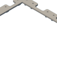
Step 5: The Watergrid


To construct the watergrid, the following parts will be needed:
Parts
- 4x M5x30 bolt
- 4x M5 locknut
- 8 mm water tube with length of approx. 80 cm.
- 10 mm waterhose tube with length of approx. 50 cm.
- 60 mm PVC tube with a length of 220 mm.
- Left Pipe connection (3D print) [Consists of 2 parts]
- Right side pipe connections (3D print) [Consists of 2 parts]
- 6x water barier (3D print)
- 6x plant cup (3D print)
- Glue suitable for plastics (PVC-glue is recommended)
First drill out 2 holes of 40 mm in the PVC pipe, 60 mm from both sides. Then cut the panels (with the holes in them) out of the PVC tube. From the centre cut out a panel with a length of 190 mm and a width of 50 mm.
Before assembling the watergrid, keep in mind that:
- All parts that will be glued are sanded.
- Dryfit all parts before gluing.
- Put the watergrid in the fridge while gluing to make sure everything alligns propperly.
- When using PVC-glue make sure to glue it quickly as the glue will dry in a few seconds. (Because of our tight fit we chose to glue the parts after putting them together. We put a bunch of glue around the edges to make sure all parts were secured to eachother and to make sure everything was watertight.)
Follow the steps in the attached video to assemble the watergrid.
After the glue has dried, use water to test if the watergrid is watertight. Pour water in the top tube and put a bucket underneath the watergrid. Also, make sure no electronics are nearby!
The complete watering network
A schematic drawing was made to give a indication on what the whole watering network will have to look like. The watering network is simulated by using a 5L jerry can. The couplings that are used can also be used on a standard water network pipes instead of the jerrycan.
- Connect the watering network by using flexible tubes and couplings to the valve.
- Connect the valve to the reservoir using the same types of couplings and tubes.
- Place and fix the positions of the 12V reservoir pumps.
- Connect the ingoing tube to the watering grid.
- Lead both the outgoing tubes from the grid and the condense catcher back to the reservoir.
- Place the capacitive water level sensors on the outside of the reservoir. Place the top sensor on a height so that 4 liters of water within the reservoir can reach the sensor.
The nutrient and pH canisters are also part of the watering grid. The second schematic drawing shows how to set up the automatic controlled nutrient and pH pumps.
- Dril a Ø4mm hole in the cap of a canister.
- Measure the needed length of the flexible tubing.
- Take off the rotating top of the motor and thread the hose arround the mechanism.
- Attach one end of the tube to the reservoir and one end to the flask.
- Optionally glue the tube to the cap.
- Repeat the proces for all three flasks.
Step 6: Water Reservoir & Interface


Additiontal information for the bottom interface 3D print
The bottom part of the water reservoir interface has m3 nuts embedded inside it. In order to make this possible the print has to be paused at a certain height. Additionally, make sure supports are turned off for this print. A pause height of 5.6mm is recommended. When the print is paused, the nuts can be placed. Afterwards, the print can continue normally, embedding the nuts within the print.
To construct the water reservoir and its interface, the following parts will be needed:
Parts
- Jerrycan
- Pumps
- Top interface of the water reservoir (3D print)
- Bottom interface of the water reservoir with embedded m3 nuts! (3D print)
- Water supply interface (3D print)
- Sensors holder (3D print)
- Nutrients & pH fluids interface (3D print)
- Drainage pipe (3D print)
- Pump tube interface (3D print)
- m3 nuts and bolts
Cutting the jerrycan and drilling holes
A big square opening will have to be cut in the jerrycan. This opening will be 122x92 mm. The opening's 'bottom' is 74 mm away from the underside of the jerrycan. The opening's sides will both be 29 mm away from the sides of the jerrycan.
Additionally the top interface can be used to mark down the positions for the m3 bolts, so that they can be drilled. Note that the interface can be held in place by the corresponding holes in the wooden plate. The jerrycan will probably have a lot of give, so support it while you're drilling the holes.
Attaching the interface
When the opening is made and the holes are drilled, the water pumps, as well as the bottom part of the interface can be placed in the jerrycan. Make sure the tube of the waterpump passes through the correct hole on the top part of the interface.
When everything is prepared, simply pull up the bottom part of the interface to the opening, match it up with the top part and screw in a bolt. The bolt will automatically tighten as you turn it, because the nut in the bottom part can't turn. Repeat untill the the interface is safely and tightly secured.
Afterwards, the interfaces for the individual parts can be attached to the main interface.
Step 7: Lighting

parts:
- 2x 1m LED strip 144 LED/m
- 2.5m of wire in 3 colors
- tape or glue to attach wire to the fridge (preferably black tape)
To provide light to the plants LED-strips have been installed on the roof and inside the door of the AIGB.
The following steps should be taken to assemble the lighting:
- Cut both the LED-strips in half and lay them down next to each other, aligning the cut ends with eachother. Solder the cut strips back together using wires of at least 30cm for one set, and at least 3 cm for the other.
- Solder the strips together at one end, using wires of about 40cm. After that, solder the rest of the wiring to one of the 2 open ends of the combined strip.
- Test the fit of the LED-strip in top of the AIGB2.0, 90 mm from the front. Make sure everything aligns properly and that the cable is on the left side. test the fit of the second pair of LED-strips inside the door next to the glass on both sides.
- Pull off the plastic from the tape and attach the strips to the top of the AIGB2.0 and inside the door.
Step 8: Mechanical and Electrical Test
Before implementing the software into the AIGB 2.0 all electrical and mechanical components need to be checked thouroughly. This can be done by the following steps:
1. Check all mechanical components by making sure they are all secured properly.
2. Check if all electronic components work properly by using a multimeter.
3. Connect the system to a 24V power source. Make sure the system is connected through a 5A fuse to make sure the system doesn't overload.
Once these steps have been completed software can be implemented into the AIGB 2.0.
Step 9: Software


The software for the AIGB consists of 3 parts:
- Libraries for sensor readings
- Actuator control
- Online dashboard connection
All software runs on a Raspberry pi 4, which can be controlled with Python. Further explanation on how to set up the software can be read in the README file on GitHub (link below).
The AIGB main code
In short, the mainv2.py code consists of a main while loop. This loop calls the method read_sensors() which returns the numeric values for the CO2, EC(nutrients), pH, temperature and humidity using the corresponding libraries. The water level sensors give a digital signal and therfore don't use a library.
After reading and assigning the sensor values to the corresponding varriables, the actuators are controlled according to the AIGB2.0 internal system conditions. The AIGB2.0 software is designed for the growth of basil plants. The AIGB2.0 is per-set with the optimal conditions for basil.The controller of the basil plant profile look like this:
- The CO2 values is read, but no further actions is taken. The CO2 is not controlled within the AIGB2.0.
- The conductivity of the water is read. The threshold lies between 320 - 608 ppm. Whenever the nutrients in the reservoir are below 320ppm, the green 12V pump is toggled on until the ppm reaches 500 ppm.
- The water level of the water level in the reservoir is read. Whenever the level_low sensor is false, the valve is opened so that the reservoir is filled. The reservoir is filled until the level_high sensor is high. The total capacity of the reservoir is 5L. The level_high sensor caps the filling of the reservoir to 4L, because arround 1L is circulating within the watering network.
- The threshold for the pH value lies between 5,8 - 6,2 pH for ideal basil growth. Whenever the pH is lower, the yellow 12V pump adds a 7ph fluid until the pH reaches 6 pH. If the pH in the reservoir is too high, a 4 pH fluid is added until the it reaches 6 pH.
- The temperature is kept below 32 °C. Whenever the temperature exceeds this threhold, the peltier element is toggled on.
- The humidity is kept below the threshold of 60%RH (relative humidity). The humidity is kept low by toggled the fans on whenever the threshold is exceeded.
- The day and night cycle gives the basil plant 14 hours of light. Therefore the lighting is turned on from 08:00-22:00.
The sequence and activity diagram also describe the structure of the main code. The main plant profile cycle can be toggled off on the dasboard. In this state, the user can overrule the actuators. As such, the user can toggle the lights, pumps for nutrients and pH and the fans.
Step 10: Dashboard
The online dashboard, created using Grafana, offers a user-friendly interface for displaying various graphs. It currently provides real-time monitoring of humidity, CO2 levels, nutrients, pH, and temperature. The graphs are fully interactive, updating every 15 seconds. On the right side of the dashboard, there's a control panel with buttons to manipulate the actuators. By default, the system is set to 'Basilicum Mode.' To manually control the actuators, switch off 'Basilicum Mode.' This allows you to adjust the LED color, fan speed, and all pump settings. Additionally, you can initiate the calibration of the pH sensor. Please note that the calibration process may take some time, but it will provide the pH readings and calibration voltage.
Step 11: Final Test and Result
To see if the current version of the AIGB 2.0 is working like the requirements and improvements demand, an acceptance test needs to be done. For this the document attached to this step can be used to determine the capabilities of the AIGB 2.0.


