Introduction: Build Your Own Universal Remote Controller That Can Connect to Anything! | 26 Customizable Inputs for Any Project (How To)
_________________
Step 1:
A Quick Preview
For the best quality read, check out this article on my homepage here. If there's a pop-up, just simply click dismiss at the bottom. Also, don't forget to subscribe for free to support my work! :)
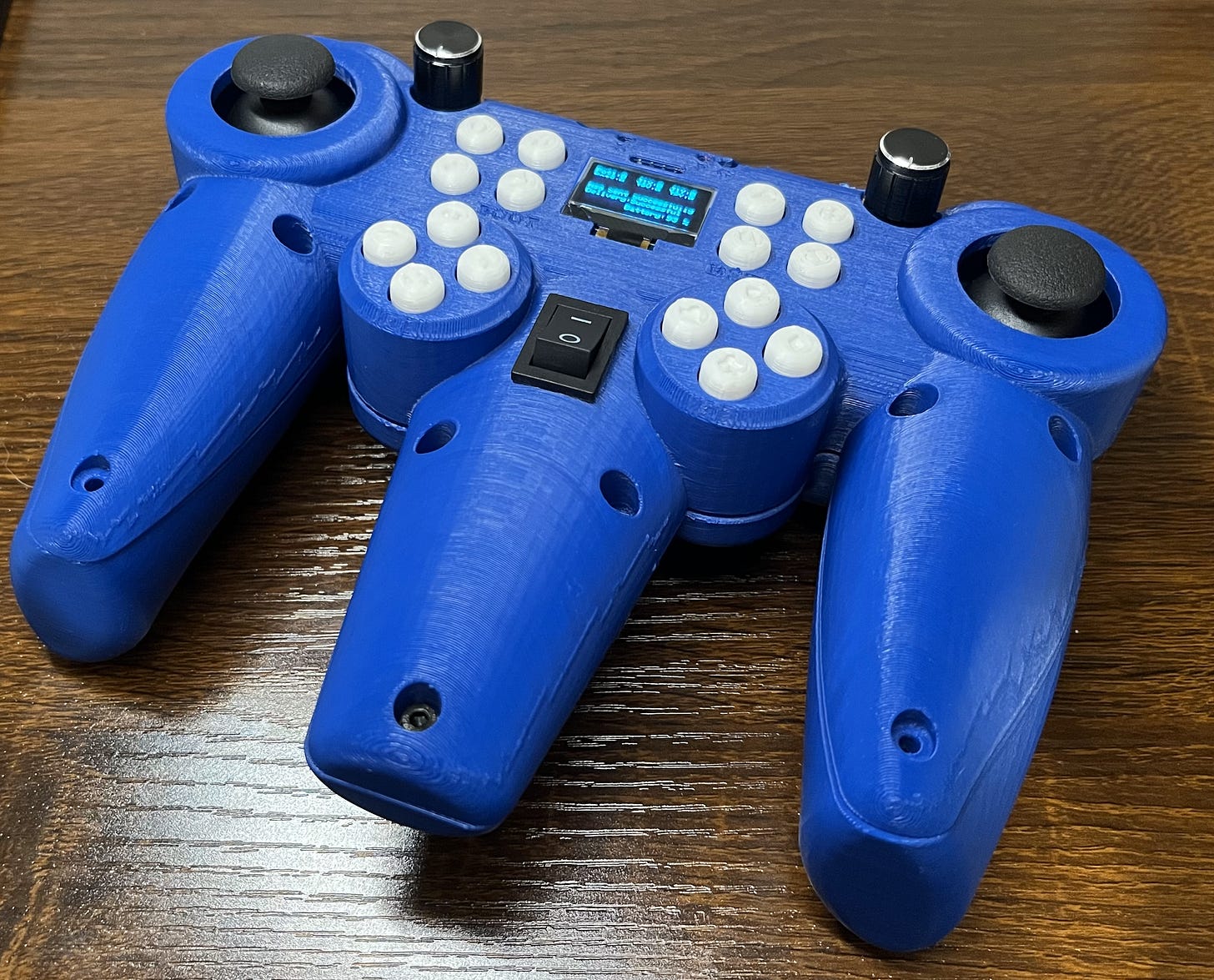
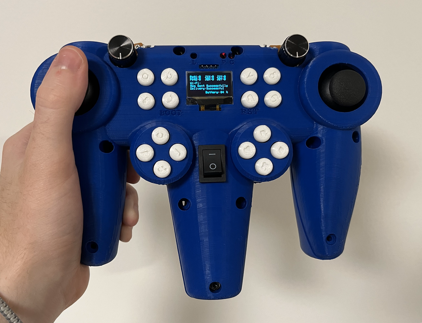
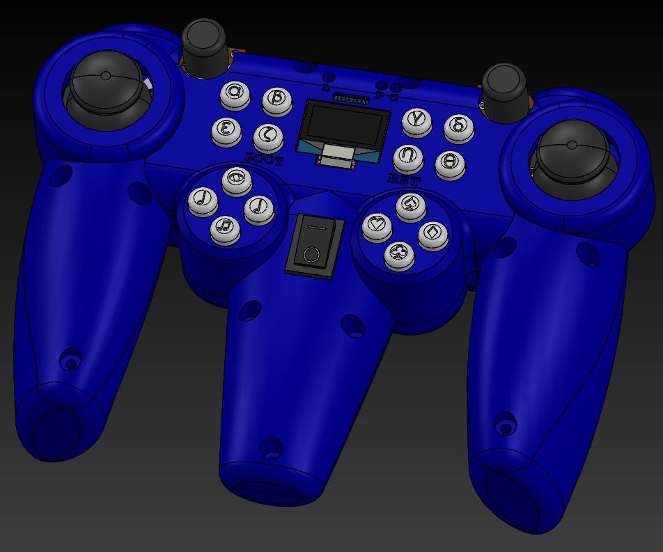
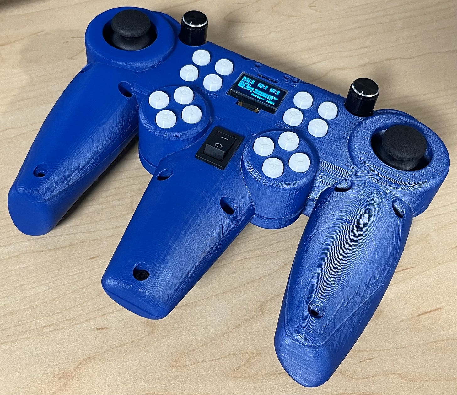
This is my universal controller. It’s equipped with 16 buttons, two potentiometers, and two joysticks each able to go up, down, left, and right for a total of 26 different inputs. It supports 2.4GHz Wi-Fi and Bluetooth 5.0 communication, perfect for controlling all sorts of wireless/IOT devices.
It has a built-in LiPo battery and charger circuit making it versatile for use. All while utilizing USB-C for wired data transfer and as a separate power source (in addition to charging the battery) in case you get low.
Step 2:
As seen above, it also has a heads-up OLED display to give you the battery level, input values, and connection status so you’re never left wondering if the data was received or what the data was. In addition, it has three LED indicators for power, charge, and low battery.
But just building a controller isn’t very exciting, which is why I’m going to give you a quick preview of what we can use this project to control!
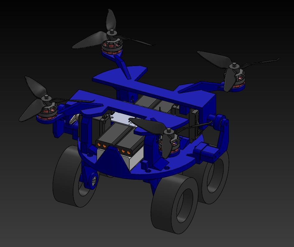
In my next project, I’ll go through the build of a super awesome, remote-controlled drone that can transform into a HOVERCAR! Okay, the car itself isn’t really hovering, but saying “hovercar” sounds way cooler than saying “land airboat.” Here’s a quick preview of the second part of this project (early stages), in which we will use the universal controller (first part) to pilot!
Step 3:
Unfortunately, as this is just a preview and I didn’t want to delay the controller portion any longer, I haven’t had stable flight work yet. (Although I’ve crashed it three four times trying to get an okay demo for you all haha.) I need some more time to develop it as well as add proper balancing and position feedback. It has plenty of power to lift off, just needs some more calibrating.
Step 4:
But don’t worry, I’ll have the flight portion up and working soon. Feel free to check my Instagram for updates. In the meantime, some other cool uses of this project are:
- When driving it on land, the propellers create an unbalanced force (air is independent of the car) so it is always going to accelerate up until it hits terminal velocity. This being said, if you drive it on a long/straight road, it can get going super fast! (Fnet = ma)
- You can redirect the blades up just a little while driving it to allow it to better traverse slopes and even stabilize itself on uneven terrain.
- This can also be useful on rough terrain where the wheels may get stuck (e.g., mud/sand). Although, I suppose you could always just fly over it if you’re okay with spending the extra power.
- Airboattttt!! (Just mount it on something that floats.)
Obviously, as I said above, the hovercar is still a work in progress. This is just a quick preview/proof of concept. In the final version, I’ll have a nice PCB to replace all the wires, flight up and working, gyro-feedback, as well as some other fixes to make it slicker and more efficient.
Hopefully, now you’re feeling pretty hyped! Don’t worry, I’ll have part two out soon. In the meantime, let me walk you through the build of this awesome controller! And naturally, you can use this controller for just about anything. You could even connect it to E.R.A., the Everything Robotic Arm, from one of my previous projects.
Working Concept
The main idea here is that a microcontroller reads all the different button inputs by sensing if there is a current at that location. If there is it’s a 1, if not it’s a 0.
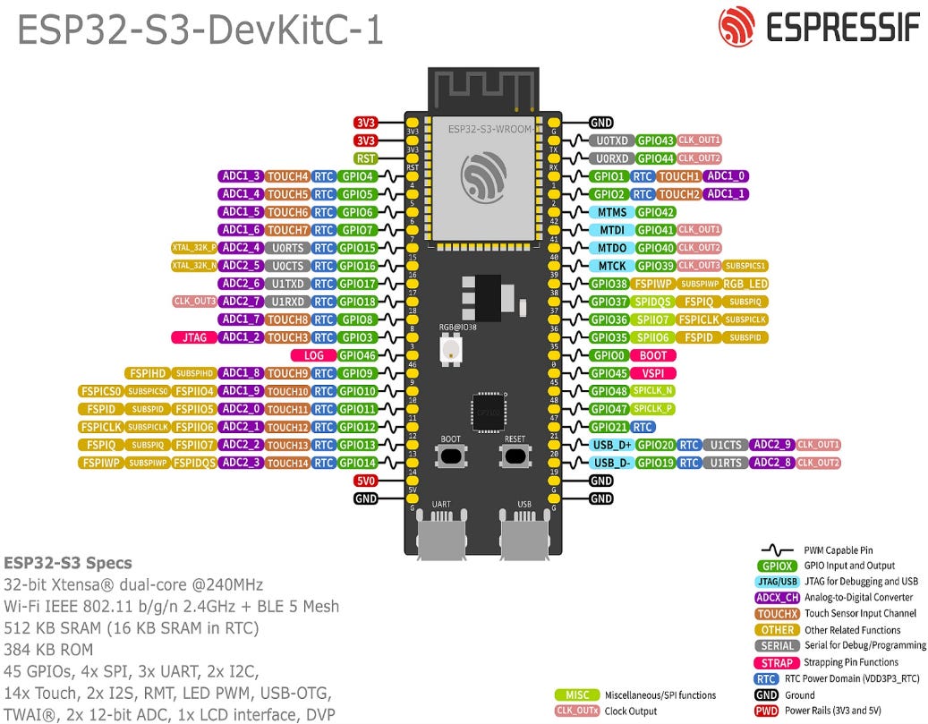
For the analog inputs, such as that in one of the potentiometers or joysticks, the microcontroller performs an analog-to-digital conversion or ADC. This turns the signal into something that the microcontroller can read properly, which we can extract data from. However, not every pin can do this which is why you may see the letters “ADC” on some pins and not others. It signals that it is an analog-to-digital conversion-capable pin.
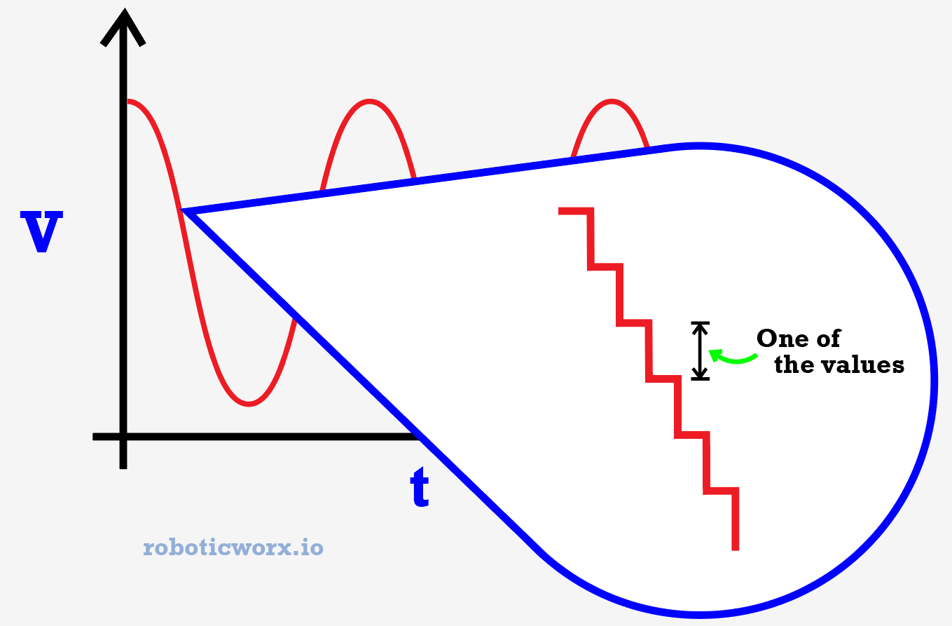
Analog-to-digital conversion works basically by first setting a reference voltage (normally the supply voltage) and then taking samples of the analog voltage at specific time intervals. By taking samples only at specific, timed intervals, you get an instantaneous value of the analog voltage at that point in time.
If you do this a lot, you get a nice range of digital voltage values that correspond to the original analog wave. These instantaneous values are all then mapped and compared to the reference voltage as the “max” with the given resolution of the microcontroller. In the case of an ESP32-S3, the resolution is 12 bits, meaning it can represent a possible 4095 different values (2^12).
This is what the waveform looks like to the microcontroller.
Then, all that’s needed is to send all of these values from the microcontroller’s antenna to whatever we want to receive the data. I normally use ESP-NOW to do this, which utilizes Wi-Fi, but you can do it however you’d like. :)
*Image from Espressif’s official website.
Getting Into the Circuitry
The circuit consists of mainly our ESP32-S3 microcontroller, a low-dropout or LDO regulator, a LiPo charger IC (more on that later), and all of our buttons, joysticks, etc. Here’s the schematic:
A higher-quality image can be found on my GitHub here. You may notice that on the part list, the 10uF caps are rated for 16V instead of 25V. Either works great, as we won’t be exceeding much more than 5V for this circuit. Editable board files can be found in the BOM.
If you’re interested in learning why there are capacitors, resistors, diodes, etc. in the places that there are, they’re normally explained in the datasheets for each part. Check them out here:
- ESP32-S3 datasheet
- Additional documents are linked on this page.
- LiPo Charger (BQ24090DGQR) datasheet
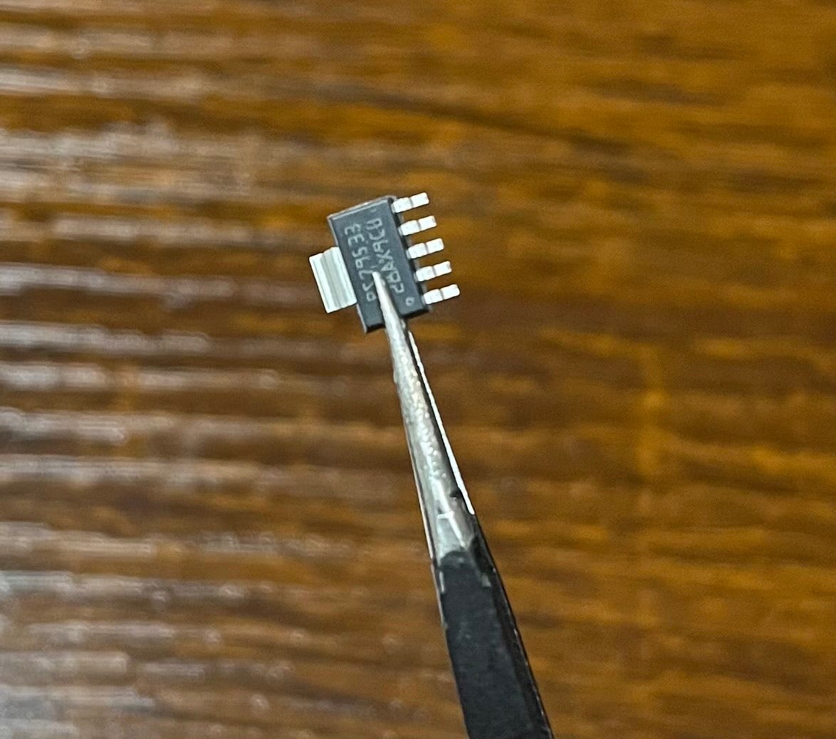
- Voltage Regulator (TPS79533DCQR) datasheet
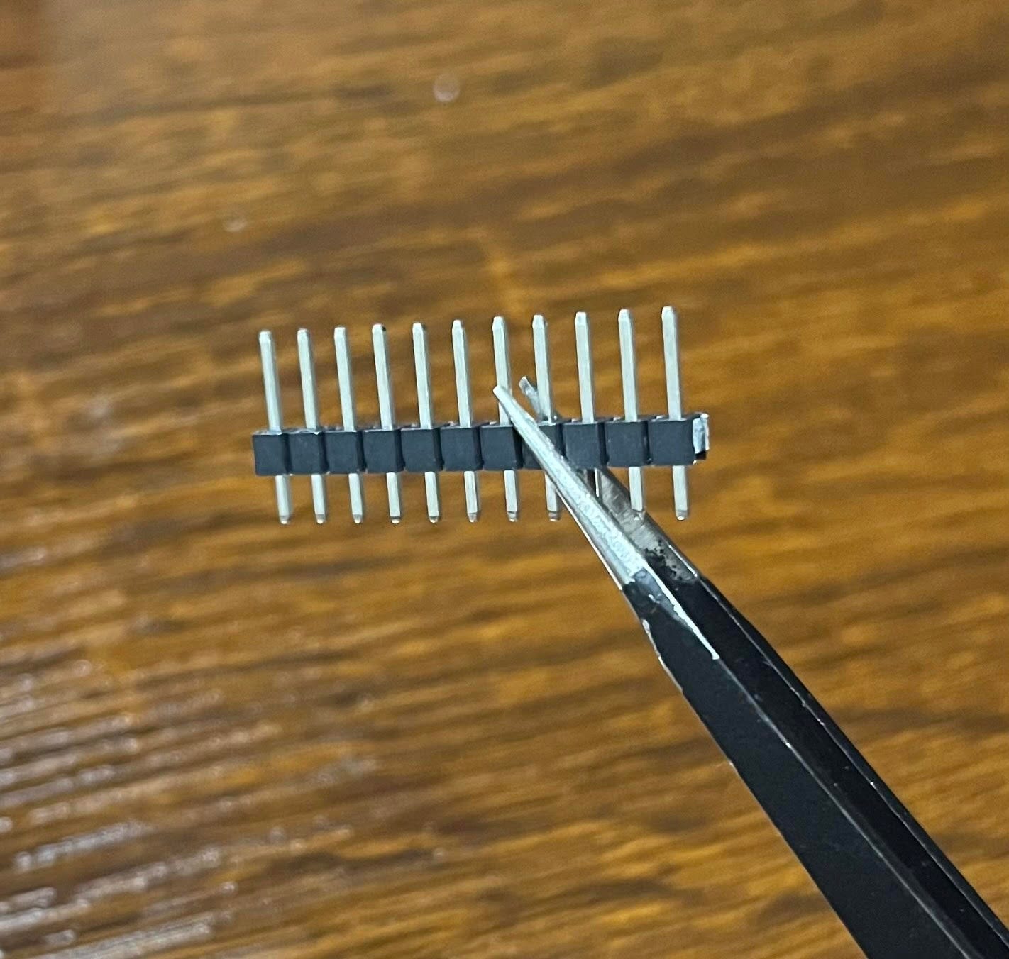
If you’re confused about why everything at the bottom looks so similar it’s because it is. They’re all just pin headers that connect externally to the joysticks, OLED display, etc.
You may have noticed a few new adds to the circuit compared to our default ESP32-S3 microcontroller circuit like that in my Solder Sustainer project. One is that I had to switch the voltage regulator from a standard AMS1117 to a TPS79533DCQR, which is a low-dropout regulator. Basically, when you step down a voltage level through a voltage regulator, there is a minimum voltage difference that is required to have a stable output. In the case of an AMS1117-3.3, this is 1.3V, making a 5V power supply perfect as 3.3 + 1.3 is less than 5.
In electrical engineering, it is common to place a “V” where the decimal point should go instead of at the end. This is to signal that it is a unit of voltage as well as to make the decimal point more visible.
The problem with our circuit is that the LiPo battery we are using only has one cell meaning it supplies 3.7V, so this regulator wouldn’t work (3.3 + 1.3 > 3.7). We would need a voltage regulator that can still step the voltage down to 3.3 but requires a smaller dropout voltage. Thus, the TPS79533DCQR was born.
Something else new is the BQ24090DGQR LiPo charger IC. Lithium Polymer, or LiPo, batteries are great because they are rechargeable but are also quite fragile. One-cell LiPos require a very specific 4.2 volts when charging and also need to be constantly monitored so that they do not overcharge and damage themselves. The best way to approach this is to use a separate IC, or integrated circuit, to charge the LiPo while also monitoring the voltage and temperature of the battery.
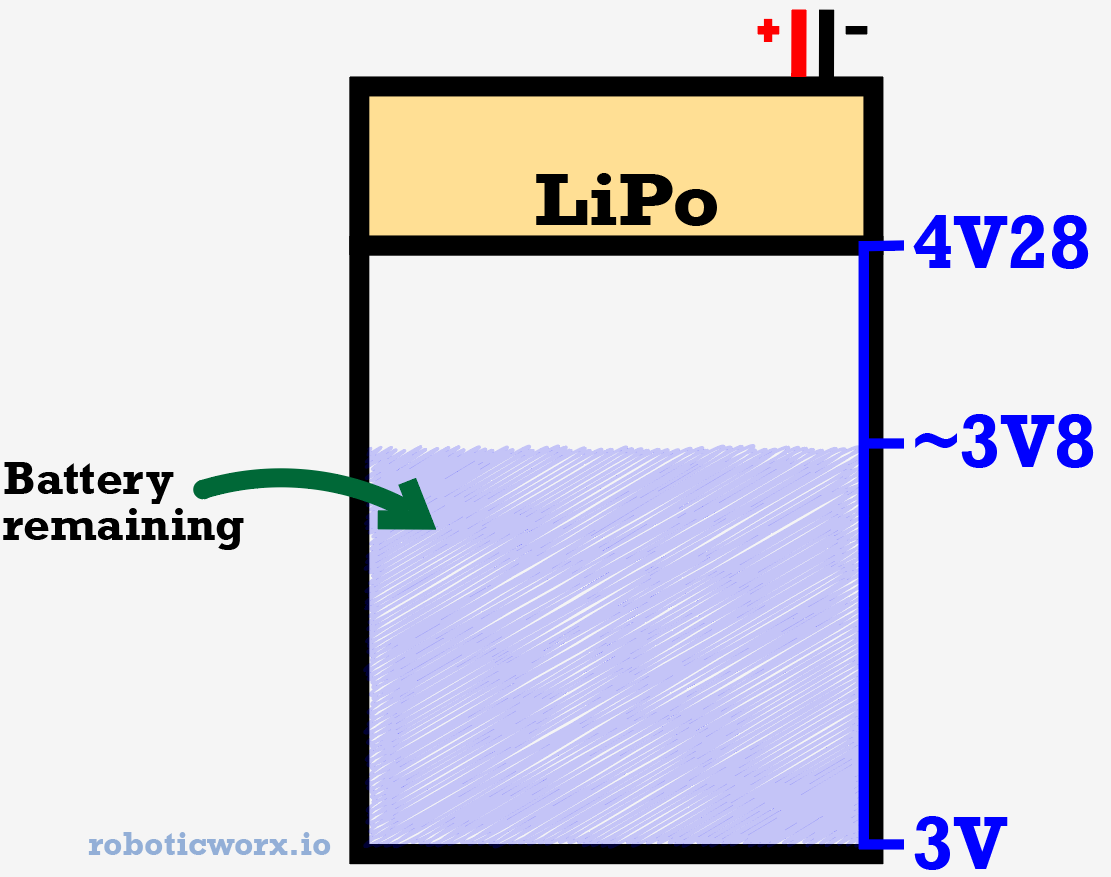
The voltage should be monitored because the charge of the battery is proportional to the voltage level, meaning when the battery is full the voltage will be at its peak. When the battery is empty, the voltage will be at its trough.
The “high” and “low” voltages differ depending on the battery.
I chose the BQ24090DGQR for this task because it seemed relatively simple to integrate and also had programmable charge rates which is nice for use in versatile situations where fast or slow charging may be preferable.
Isn’t it tiny?!
That’s about it for the new additions except for the small voltage divider I placed at the LiPo voltage input pin. The reason for this is that the LiPo is rated for 3.7V, and when overcharged can even reach 4.28V, which is much higher than the reference voltage we discussed earlier when talking about ADCs. If we want to be able to read the voltage level and turn on a small LED when it’s time to charge, we need a way to reduce the voltage.
Basic voltage divider circuit.
A voltage divider is more efficient than a voltage regulator in this case because we don’t want the output voltage to be fixed. We want it to change as the battery level gets lower so that we can detect it. For this reason, a voltage divider is efficient. Plus, it takes up much less space.
Building the Board
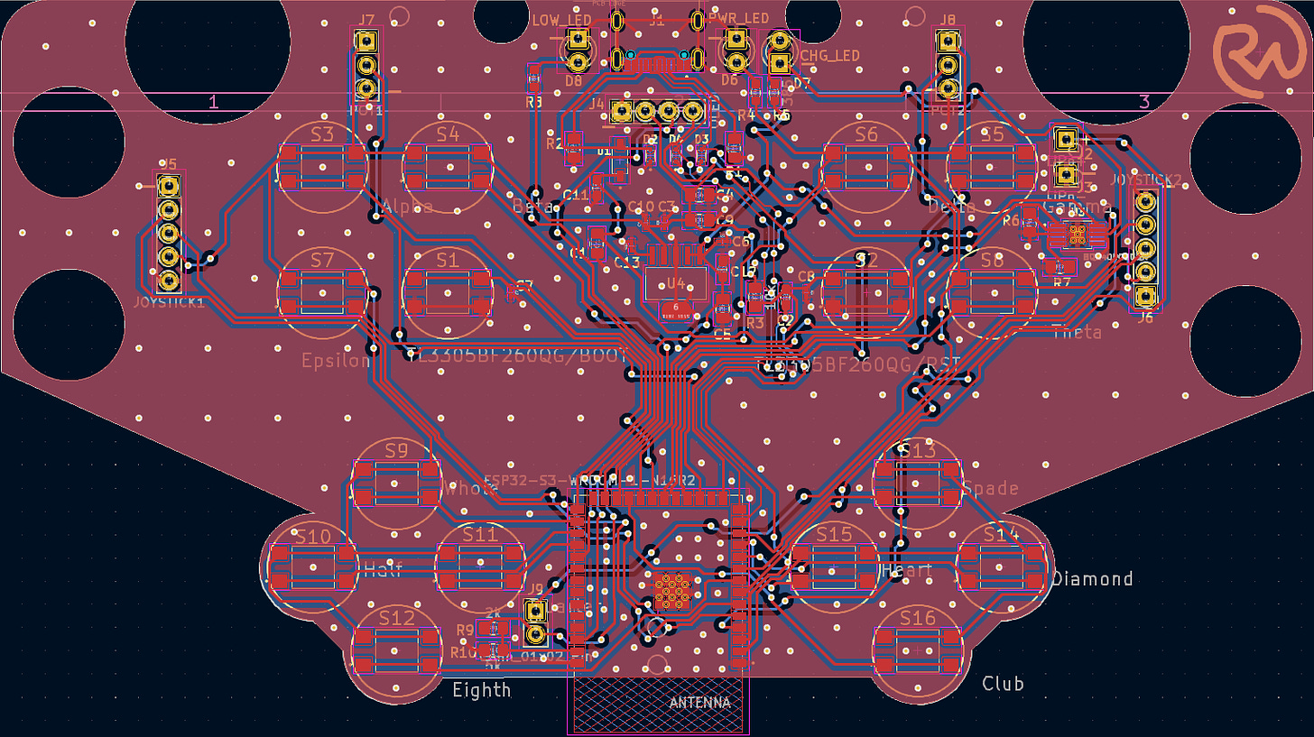
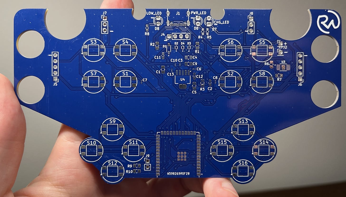
This is what the final layout looks like.
- The Gerber/fabrication file for the board can be found here on my GitHub.
- The editable KiCad files for the board can be found here.
- The part list for all the components required in this circuit can be found here.
- I know that it can seem like a pain to have to order parts, but let me explain why it’s not! Almost all the parts I order from one project get reused. For example, I only had to order two parts for this project (the special LDO regulator and LiPo charger IC). Everything else was easily reused from previous projects, as almost everything is the exact same every time when using the same microcontroller (the almighty ESP32-S3)! That being said, you only really have to order parts one time and you’ll be set for many projects to come. So, buy in bulk, and please don’t feel intimidated by them. Think about how much you’ll learn!
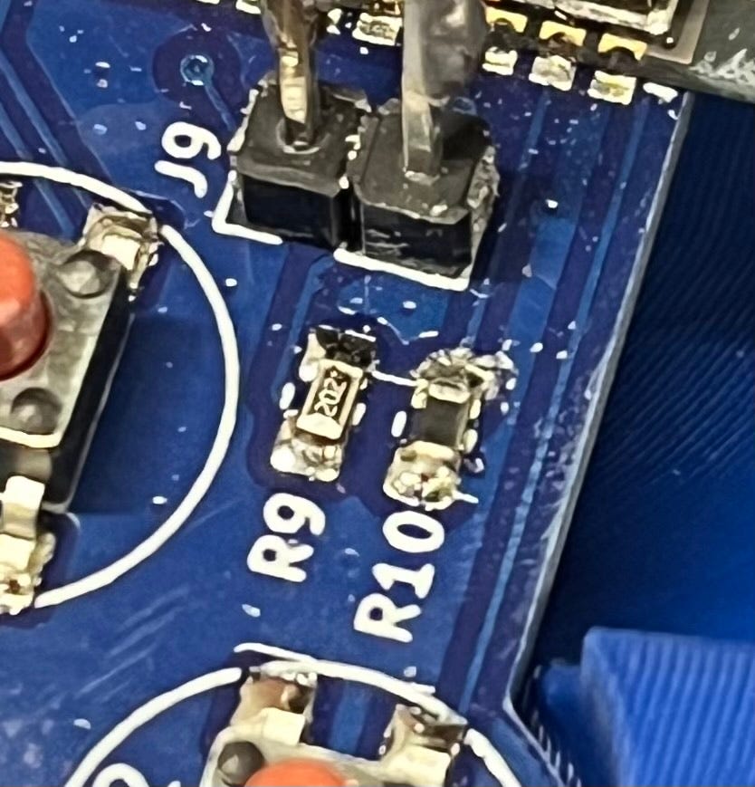
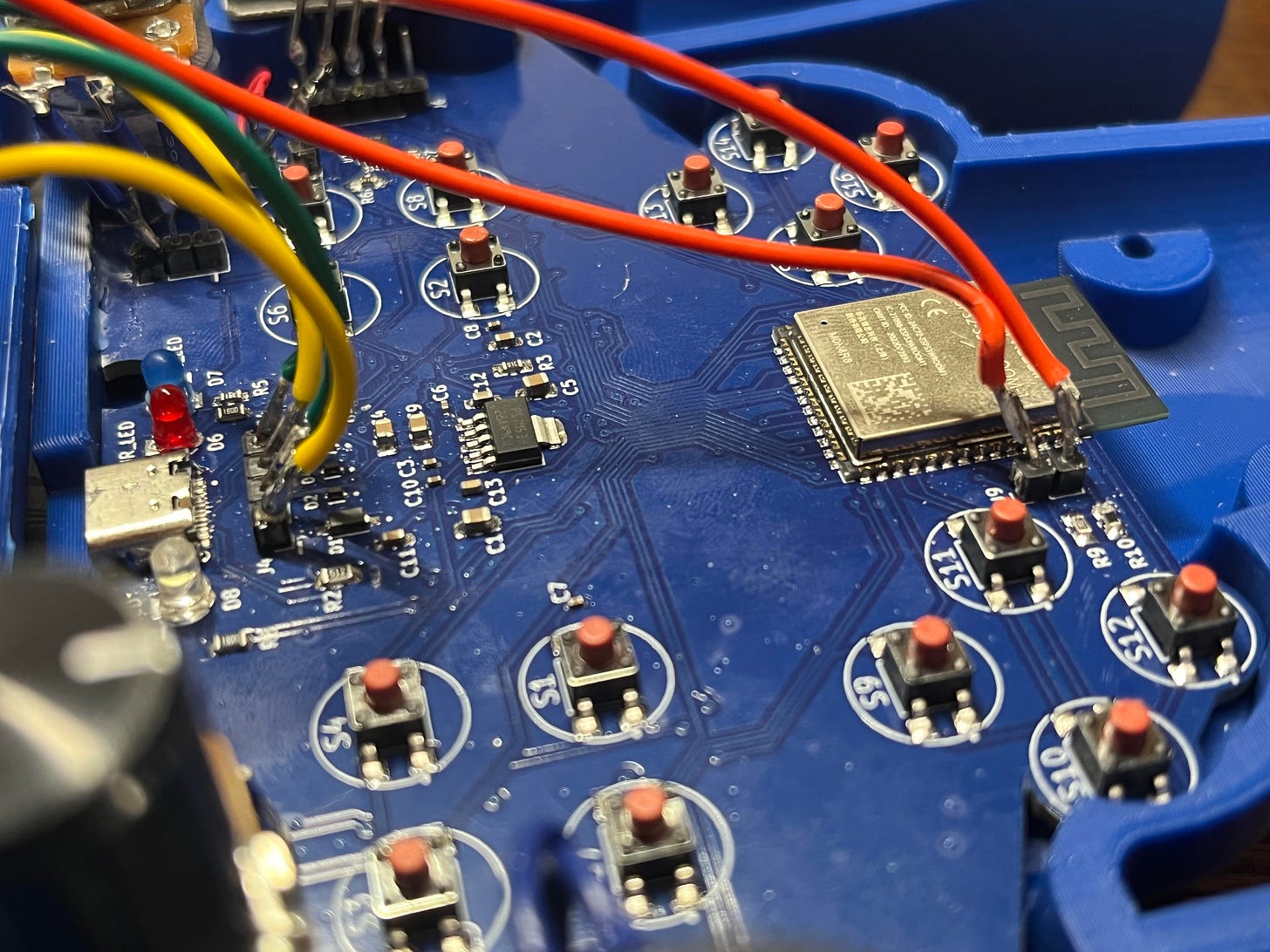
You may notice that I had to make a small change during the layout from what was in the circuit schematic. I decided to disconnect the temperature-sensing pin from the LiPo charging IC because after looking at the sheer size of the ground plane, I didn’t think the temperature would be much of a problem. Instead, I connected the temperature sensing pin to a GPIO (General-Purpose Input/Output) pin of the microcontroller so I could control it directly, as pulling the pin low disables the IC. All this really means is now the LiPo charger circuit looks like this:
As nice as it would be to be able to build this circuit at home, it would be far too complex and there would be no way to fit it into such a tight space. Because of this, we need to go through a PCB manufacturer. As usual, PCBWay was my go-to!
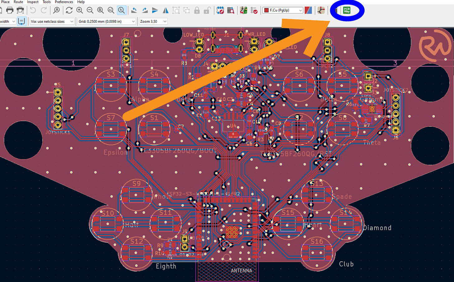
Their quality is always fantastic. Plus, they even have a super neat KiCad plug-in so I can check out without even leaving my ECAD (Electronic Computer-Aided Design) software.
All I had to do was install their plug-in, and then hit the PCBWay button once I was done!
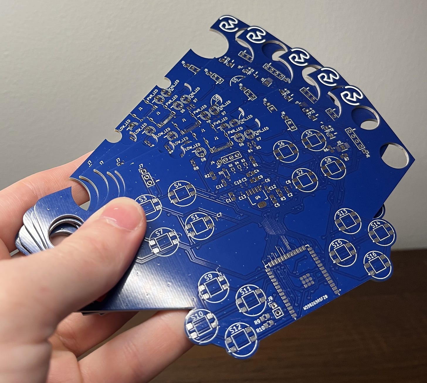
Once the boards arrived just a few days later, they looked beautiful.
Now it was time to get to assembling it. I recommend purchasing a Stencil at PCB checkout to make this step much easier.
First, you’ll want to line up your Stencil with the pads of the PCB. Then, you can apply solder paste over the top of the stencil and spread it into the pads. I used a 3D printer scraper for this.
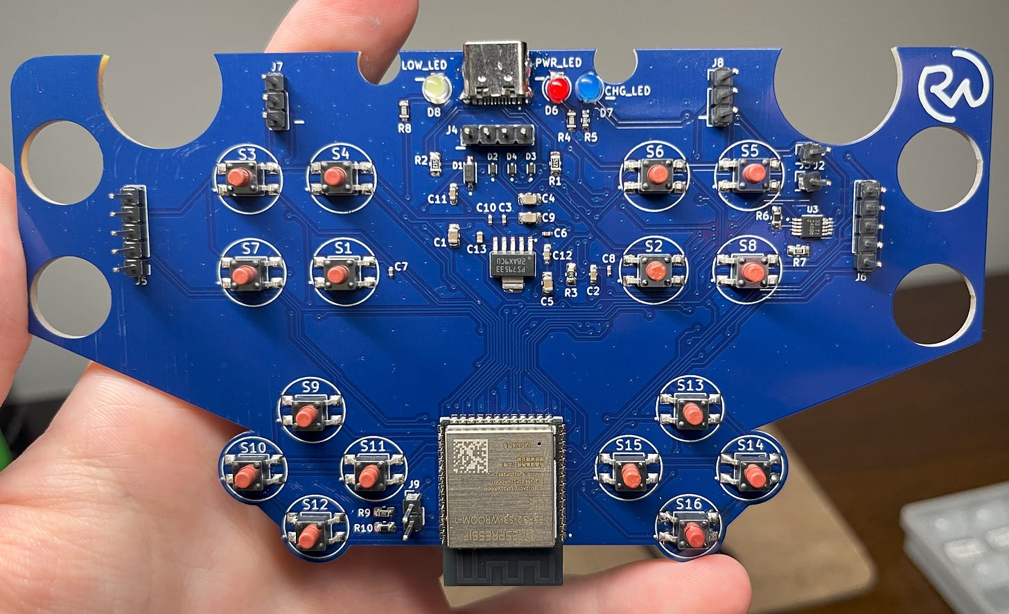
Then, you’ll want to place all the components. You should print out this reference sheet so you can match the SMDs (Surface Mount Devices) with the numbers on the board.
Then, apply some heat… and voilà!
Here’s a short video outlining the process:
Step 5:
NOTE:
- Before uploading any code, you need to put the board into bootloader mode. You can do this by holding down the boot button (S1) > hitting the reset button (S2) while it’s held > and then releasing the boot button (S1).
- When connected, if the OLED display doesn’t turn on upon supplying power to the board, just hit the RST button (S2).
Assembly
With the PCB built and operational, it’s time to get to mounting it to the 3D-printed controller along with all the other components.
All the CAD for this project can be found here on my Thingiverse for free!
All the parts and everything else you may need can also be found in the BOM.
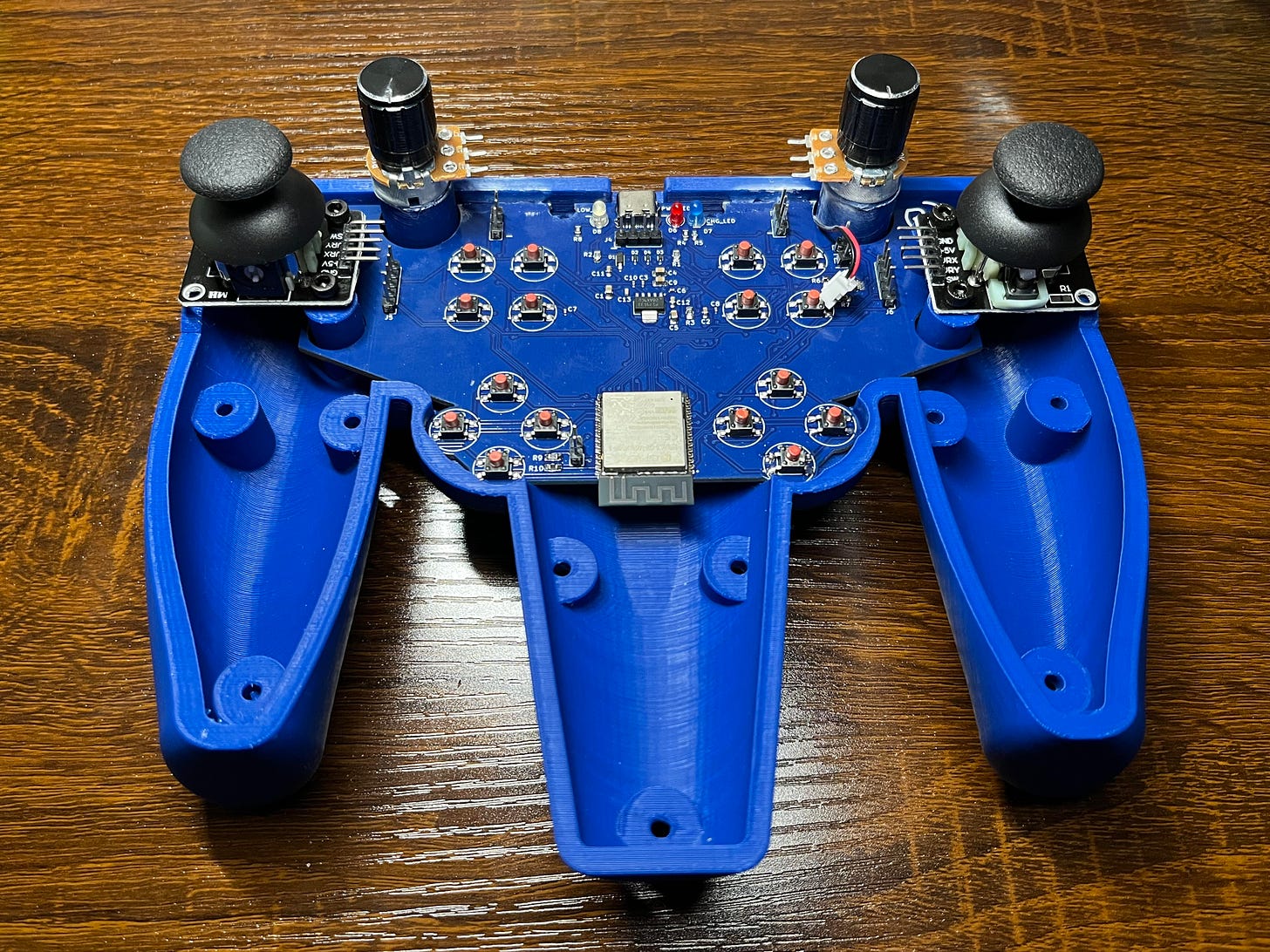
First, take the bottom half of the controller and pop in the small LiPo battery. It should fit snugly into its slot. Make sure that the battery is oriented so that the wires come out of the indention at the top right.
Forgot to take the real photo and everything’s glued lol. (Sry! But just pop it in EZPZ.)
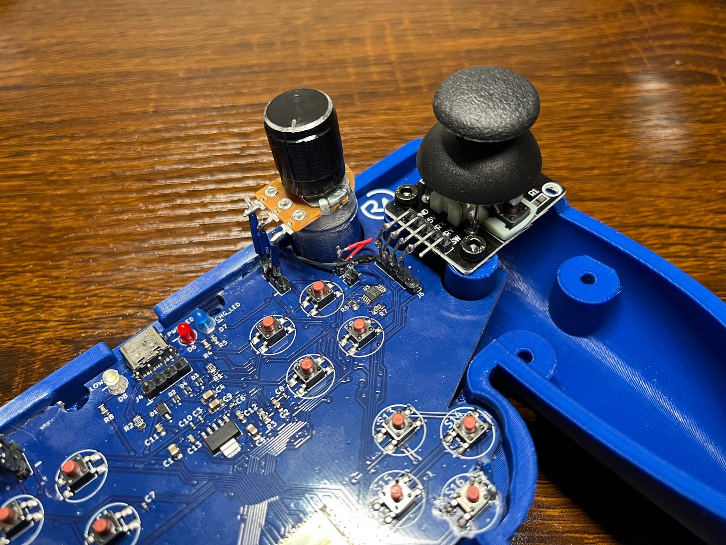
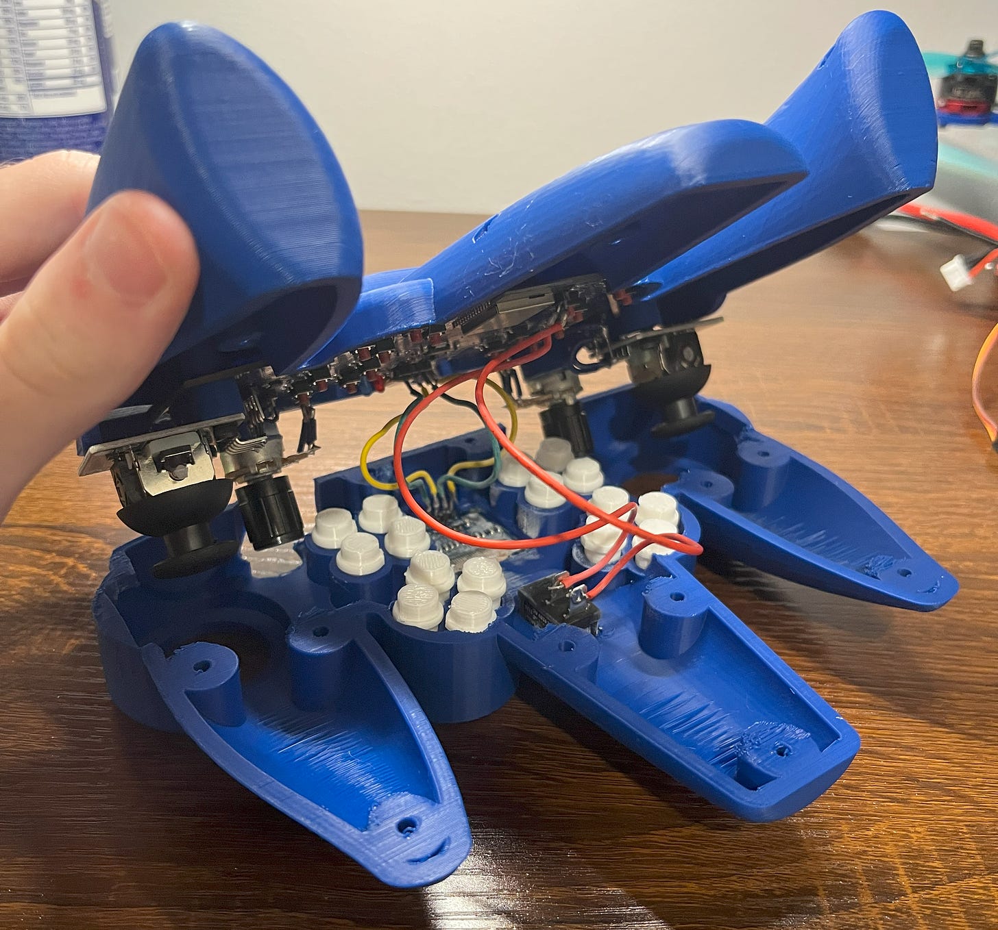
Then, grab and place your newly baked PCB. It should slide right on. From there, grab your two joysticks and screw them in as shown below. The potentiometers can then be super-glued in position, just be sure they are 90 degrees with the controller or less.
Next, break out your soldering iron and connect up the joysticks and potentiometers. They all connect with the pin headers directly below them so it should be fairly simple. If you built my Solder Sustainer project, this step should be in EZ mode. :D You can also go ahead and connect up the LiPo battery. The pins are labeled with a “+” and “-”.
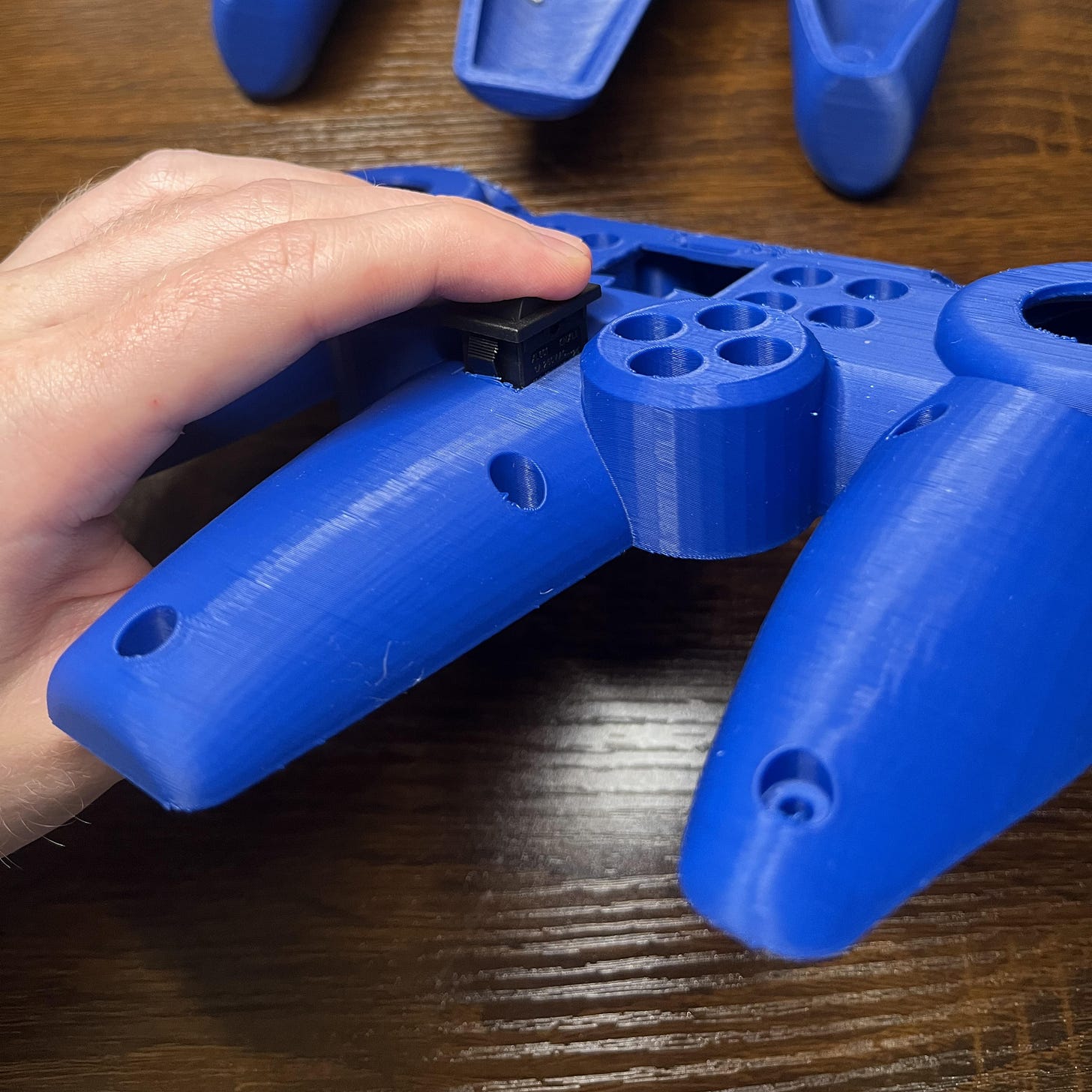
Then, grab the top half of the controller and push in the switch. It should snap right into place.
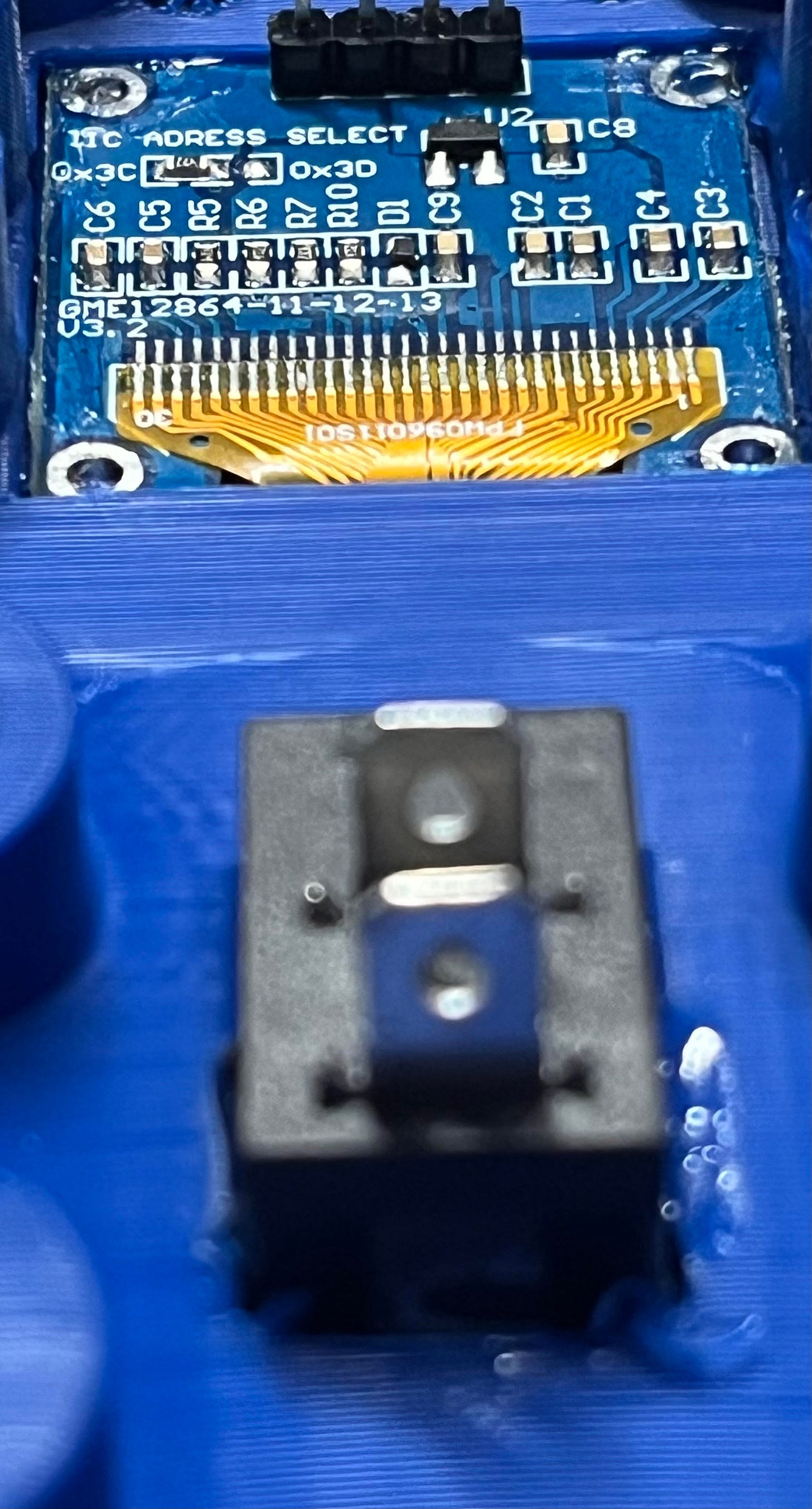
With that, flip over the top half of the controller and pop in the OLED display. After it’s in position, you can secure it with some super glue. I put some on the switch too, because why not?
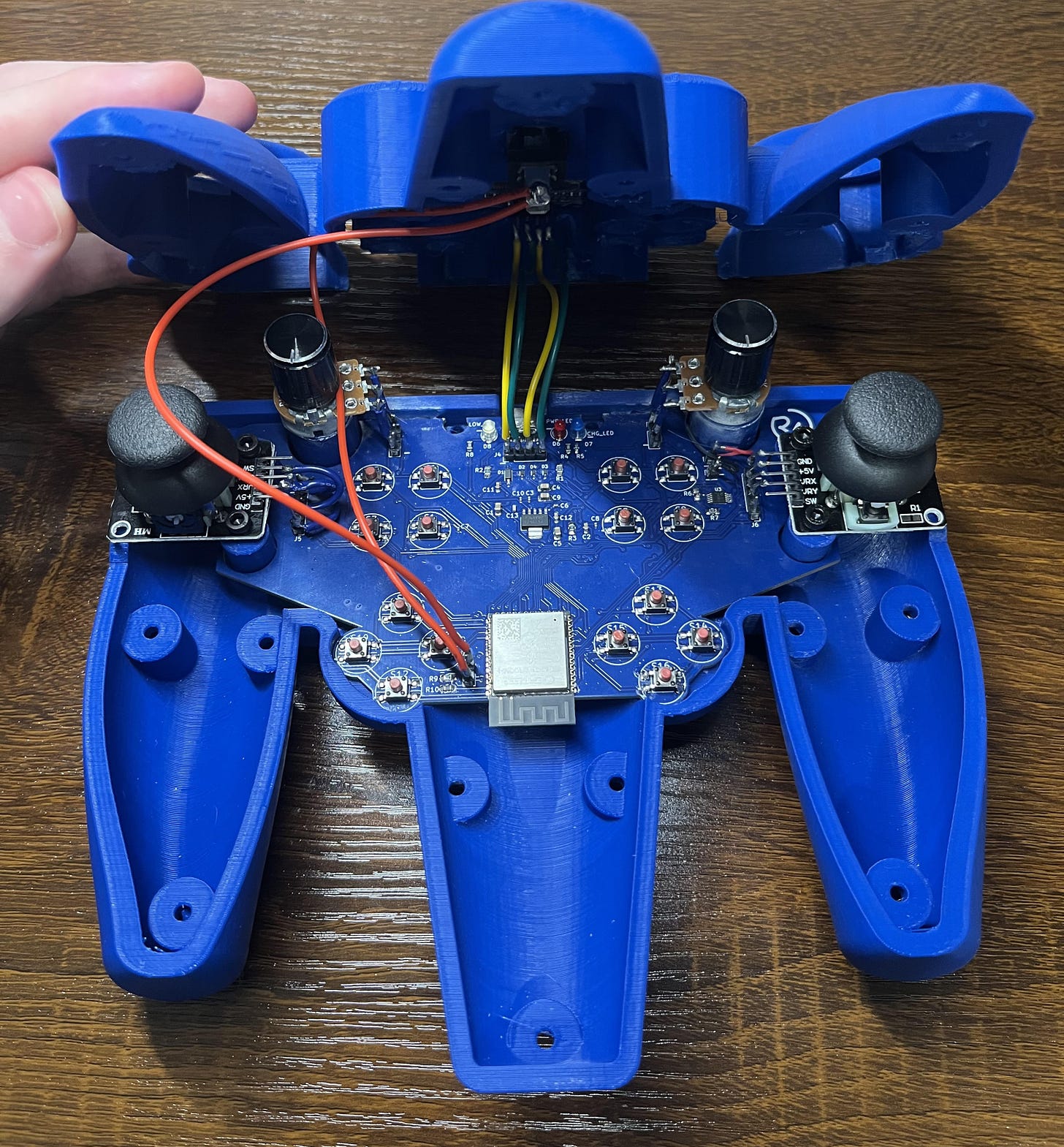
Again, grab your soldering iron and solder on some wires to connect up the switch and OLED display with the PCB. The polarity of the switch doesn’t matter, and the OLED wires connect straight-on given you connect them so the top half is mirroring the bottom.
I recommend bending the pin headers a bit as shown below so that the top half will fit better when you eventually connect the two.
Then, grab your many buttons and pop them into the top half, face-down. I put some cool designs on the top of each button to set them apart. First are the Greek letters (alpha-theta), then some music notes (whole-eighth), then finally some card suits (spade-clubs).
They’re a bit hard to see on white.
From there, you can just place the top half over it.
If the wires get in the way, you can just tuck them into the base component. It doesn’t really matter where they are so long as they aren’t between the buttons.
Then, simply pop some M3 nuts into the back and screw in the bolts! I used mainly M3x30mm bolts for this.
That’s it! :D
Programming
With the assembly complete, it’s time to jump into the programming. For this controller, I used the Arduino IDE to write and upload everything.
The full transmitter code can be found here.
First, let’s break down how the controller (transmitter) code works.
To start, we need to import all the libraries we are using. These are some graphics libraries for the OLED display and some ESP-NOW libraries for wireless communication. Then we can set the pixel height and width for the OLED and which pins we will use to communicate with it.
#include <Wire.h>
#include <Adafruit_GFX.h>
#include <Adafruit_SSD1306.h>
#include <esp_now.h>
#include <WiFi.h>

#define SCREEN_WIDTH 128 // OLED display width, in pixels
#define SCREEN_HEIGHT 64 // OLED display height, in pixels

const int I2C_SDA = 3;
const int I2C_SCL = 2;
Then, we can create the display. In addition, we can set up the broadcast address, data structure, and peer (receiver) information for using ESP-NOW.
It should be noted that you need to replace the MAC address (broadcast address) with the address to which you are sending the data. You can find out how to get that address as well as more about it here.
Adafruit_SSD1306 display(SCREEN_WIDTH, SCREEN_HEIGHT, &Wire, -1);

uint8_t broadcastAddress[] = {0x68, 0xB6, 0xB3, 0x2A, 0xA3, 0x14};

typedef struct struct_message {
  int a; // Pot1
  int b; // Pot2
  int c; // J1X
  int d; // J1Y
  int e; // J2X
  int f; // J2Y
  int g; // Button number
} struct_message;

struct_message dataSent;

esp_now_peer_info_t peerInfo;
After that, we need to assign which pins are connected to everything.
const int pot1Pin = 9;
const int pot2Pin = 10;
const int j1xPin = 5;
const int j1yPin = 6;
const int j2xPin = 7;
const int j2yPin = 8;
... all the rest
Next, we should create an array to hold all information about which button is connected where. This is more effective than just declaring all of them because there are sooooo many.
int buttons[14] = {alpha, beta, gamm_a, delta, epsilon, theta, whole, half, quarter, eighth, spade, heart, diamond, club}; // 14 becuase it holds 14 values
The next part is just a huge array to display the logo. I understand if you’d prefer not to have it on yours, (even though I think it looks cool), so you can remove it by simply deleting the code below on lines 171-174.
  display.drawBitmap(0, 0, logo_img, 128, 64, 1); // Draw logo
  display.display(); // Display the display
  delay(2000);
  display.clearDisplay();
After that, we need to set up the wireless communication. We can do this by setting the device as a Wi-Fi station, checking if the initialization succeeded, checking the status of the data, and then setting up where the data is being sent.
  WiFi.mode(WIFI_STA); // Initialize Wi-Fi

  if (esp_now_init() != ESP_OK) {
    Serial.println("Error initializing ESP-NOW");
    return;
  }
  esp_now_register_send_cb(callData);

  memcpy(peerInfo.peer_addr, broadcastAddress, 6);
  peerInfo.channel = 0;
  peerInfo.encrypt = false;
Then, you can add the peer (receiver) and declare the different pin types. It’s an input if you’re reading data and an output if you’re sending data (PWM for example).
  if (esp_now_add_peer(&peerInfo) != ESP_OK) { // Add peer
    // Can put failed to add peer msg here if needed
    return;
  }

  // Initialize types of pin
  pinMode(batteryPin, INPUT);
  pinMode(lowLedPin, OUTPUT);

  pinMode(pot1Pin, INPUT);
  pinMode(pot2Pin, INPUT);
  pinMode(j1xPin, INPUT);
  pinMode(j1yPin, INPUT);
  pinMode(j2xPin, INPUT);
  pinMode(j2yPin, INPUT);

  for (int i = 0; i < 14; i++) // Declare all buttons as input
    pinMode(buttons[i], INPUT_PULLDOWN);
Next, we need to tell the OLED display library which pins we are using for the SDA and SCL data pins to communicate with the display.
Wire.begin(I2C_SDA, I2C_SCL);
After that, we can set the cursor position, text size, and text color to start printing some letters.
  display.clearDisplay();
  display.setTextSize(1);
  display.setTextColor(WHITE);

  display.setCursor(0, 23);
  display.print("Wi-Fi:");

  displayPots();
  displayJoysticks();
  displayButtons(buttons);
The three functions used above (displayPots(),displayJoysticks()and displayButtons(buttons)) are custom functions written below the main code to allow for some organization.
- The first two basically work just by reading data on that pin, assigning it to a -1, 0, or 1 if it’s a joystick, 0-100 if it’s a potentiometer, and then assigning it to the data value that is being sent wirelessly.
- NOTE: You can feel free to change these values to whatever you’d like! For example, when I was doing some servo testing, I updated the values to go from 0-180 for the different degrees of a servo motor.
- The last function works by going through the array of buttons and checking each one to see if it’s been pressed. If it has, it displays that button’s GPIO and assigns it to the value that is being sent wirelessly.
- In addition, all of them also print out what value the data value is being assigned, so you always know what you’re sending.
Then, you send the wireless data and print to the display if the send was successful or not.
  esp_err_t result = esp_now_send(broadcastAddress, (uint8_t *) &dataSent,   sizeof(dataSent));

  display.setCursor(0, 32);

  if (result == ESP_OK) {
    display.print("Msg Sent Successfully");
  }
  else {
    display.print("Send Failed.");
  }
Now comes how the battery display works.
- Simply put, the battery indication isn’t perfect. It fluctuates with a +-5ish% tolerance just because of the imperfections with reading small voltage changes. This being said, to smoothen it out, there’s an if statement that only allows the battery to be checked and updates every 3000ms or three seconds.
- When that moment arrives, the value is mapped to a value of 1-100% with some mins and maxes on both ends. In addition, a low-battery LED will be turned on if the battery falls below 35%. (It’s not healthy for a LiPo battery to discharge below 30%!)
- The values 2742 and 3623 were calculated by getting the voltage out (min and max) from the voltage divider and then setting it to a value corresponding to 3V3 as 4095 (maximum values).
For example, the maximum voltage out from the voltage divider (when the battery is full) is around 2.92V. Therefore, the corresponding value for the microcontroller would be (2.92/3.3) * 4095, or 3623.
  unsigned long currentMillis = millis();
  if (currentMillis - previousMillis >= 3000)
  {
    batteryLevel = analogRead(batteryPin);
    batteryLevel = map(batteryLevel, 2742, 3623, 0, 100);
    if (batteryLevel > 100)
      batteryLevel = 100;
    else if (batteryLevel < 1)
      batteryLevel = 1;
    if (batteryLevel < 35)
      digitalWrite(lowLedPin, HIGH);
    else
      digitalWrite(lowLedPin, LOW);
    previousMillis = currentMillis;
  }
Then, you just display the display.
display.display();
That’s it!
I’m not going to explain the receiver code because it is so short and similar, but you can feel free to explore through this basic example here. All it does is receive the values and print them to the serial display. Feel free to incorporate it into any application!
BOM
This is the Bill of Materials for my Universal Controller project.
I’ll put everything that you need to have here so that you don’t have to go scrolling around looking for the links/parts I sprinkled throughout the article.
- The project CAD can be found here on my Thingiverse page. I’ve also attached STEP files so you can make your own edits!
- The editable KiCad (ECAD) files can be found here (click download raw).
- The board fabrication/Gerber file can be found here (click download raw).
- The SMD (tiny components) part list can be found here.
- The reference sheet for PCB assembly can be found here.
- OLED display
- Pin headers
- Joystick modules
- Potentiometers
- 3V3 LEDs
- 1400mAh LiPo battery
- Some bolts and nuts (if needed)
- Awesome/cheap screwdriver kit (if needed)
- Some super glue?
Disclosure: These are affiliate links. I get a portion of product sales at no extra cost to you.
Thanks so much for reading! I hope this was a helpful and informative article. If you decide to do the build, please feel free to leave any questions in the comments below. If not, I hope you were still able to enjoy reading and learn something new!
Have constructive criticism? I’m always looking to improve my work. Leave it in the comments! Until next time.
Be sure to follow me on Instagramand check out these projects on my homepage! :)






















![Tim's Mechanical Spider Leg [LU9685-20CU]](https://content.instructables.com/FFB/5R4I/LVKZ6G6R/FFB5R4ILVKZ6G6R.png?auto=webp&crop=1.2%3A1&frame=1&width=306)


