Introduction: CRAZY L.O.L SPECTRUM ANALYZER
Today I'd like to share how to make an audio spectrum analyzer - 36 bands by combining 4 LoL Shields together. This crazy project uses a FFT library to analyze a stereo audio signal, convert it to frequency bands, and display amplitude of these frequency bands on 4 x LoL Shields.
Before getting started, please watch the video below:
Step 1: THINGS WE NEED
The main electronic components are as below:
- 4pcs x Arduino Uno R3.
- 4pcs x LoLShield PCB. PCBWay (Full feature custom PCB prototype service) supported me these LoLShield printed circuit boards.
- 504pcs x LED, 3mm. Each LoLShield needs 126 LEDs and we can choose 4 different led colors & types (diffused or non-diffused).
- 1pcs x Portable Charger Power Bank Battery 10000/20000mAh.
- 4pcs x Male Header 40pin 2.54mm.
- 2pcs x USB Type A/B cable. One is used for Arduino programming, the other is for powering the Arduino from a power bank.
- 1pcs x 3.5mm Female Stereo Audio Jack.
- 1pcs x 3.5mm 1 Male to 2 Female Audio Splitter Adapter or Multi Headphone Audio Splitter.
- 1pcs x 3.5mm Stereo Audio Jack Male-Male Connector Cable.

- 1m x 8P Rainbow Ribbon Cable.
- 1m x Two Cores Power Cable.
- 1pcs x Clear Acrylic, size A4.
Step 2: SCHEMATIC
The LoLShield is a 9x14 charlieplexing LED matrix for the Arduino and this design DOESN'T include any current limiting resistors. The LEDs are individually addressable, so we can use it to display information in a 9×14 led matrix.
The LoL Shield leaves D0 (Rx), D1 (Tx) and analog pins A0 to A5 free for other applications. Picture below shows Arduino Uno pins usage for this project:

My audio spectrum analyzer has 4 x (Arduino Uno + LoLShield). The power supply and stereo audio jack 3.5mm are connected as below schematic:

Step 3: LOL SHIELD PCB & LED SOLDERING
1. LoL SHIELD PCB
Ѽ. You can refer to PCB design at: https://github.com/jprodgers/LoLshield by Jimmie P. Rodgers.

Ѽ. PCBWay supported me these LoLShield printed circuit boards with fast delivery and high quality PCB.

2. LED SOLDERING
Ѽ. Each LoLShield needs 126 leds and I used different kind & colors for 4x LoLShields as follows:
- 1 x LoLShield: diffused led, red color, 3mm.
- 1 x LoLShield: diffused led, green color, 3mm.
- 2 x LoLShield: non-diffused (clear) led, blue color, 3mm.
Ѽ. Preparing LoLShield PCB and LED

Ѽ. Soldering 126 LED onto LoLShield PCB. We should check the LEDs by battery after soldering every row - 14 LEDs
- TOP LoLSHIELD

- BOTTOM LoLSHIELD

Ѽ. Finishing one LoLShield and continue to solder 3 remaining LoLShield.

Step 4: CONNECTION AND ASSEMBLY
Ѽ. Soldering power supply and audio signal to 4xLoLShield. A stereo signal uses two audio channels: left and right which are connected to Arduino Uno at analog pins A4 & A5.
- A4: Left Audio Channel.
- A5: Right Audio Channel.

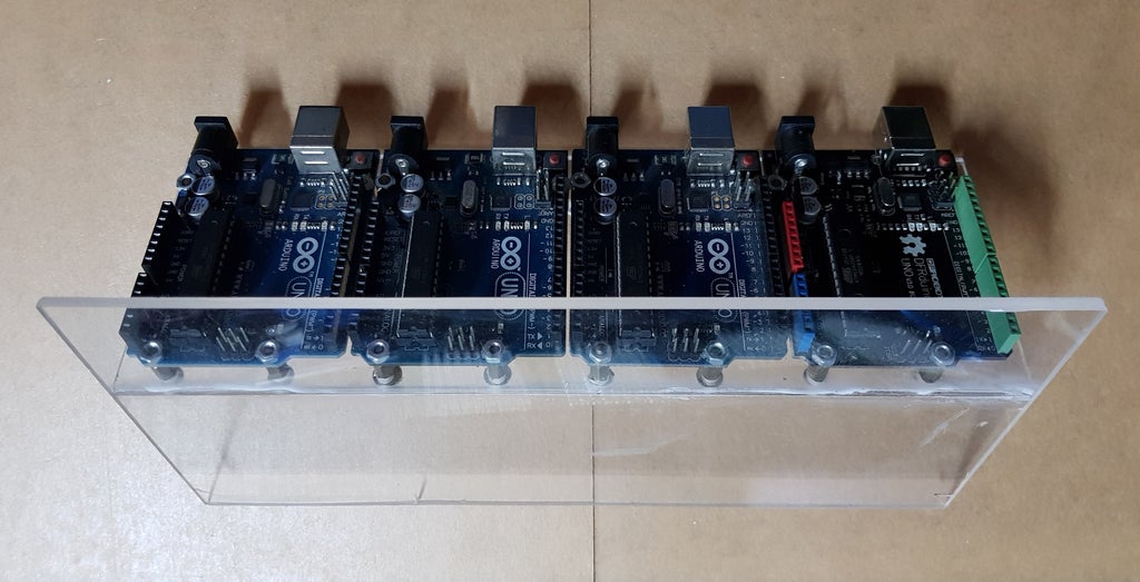
Ѽ. Aligning & mounting 4 x Arduino Uno on the acrylic plate.

Ѽ. Plugging 4 x LoLShield on to 4 x Arduino Uno.

Ѽ. Glue portable charger power bank and audio jack on acrylic plate

Ѽ. Done!

Step 5: PROGRAMMING
You should refer to how LoLShield works based on the Charlieplexing method and Fast Fourier Transform (FFT) at:
https://en.wikipedia.org/wiki/Charlieplexing
https://github.com/kosme/fix_fft
For Charlieplexing, we pay attention to the "three states" of the Arduino digital pins: "HIGH" (5V), "LOW" (0V) and "INPUT". The "INPUT" mode puts the Arduino pin in high-impedance state. Reference at:
https://www.arduino.cc/en/Tutorial/DigitalPins
In my project, the audio frequency bands are displayed on 4 x LoL Shield and they are described as shown below:

Each Arduino reads audio signal at left/ right channel and perform the FFT.
  for (i=0; i < 64; i++)
  {
    Audio_Input= analogRead(RIGHT_CHANNEL); // Read audio signal at right channel A5 - ARDUINO 1 & 2
    //Audio_Input = analogRead(LEFT_CHANNEL); // Read audio signal at left channel A4 - ARDUINO 3 & 4
    Real_Number[i] = Audio_Input;
    Imaginary_Number[i] = 0;
  }

  fix_fft(Real_Number, Imaginary_Number, 6, 0); // Perform Fast Fourier Transform with N_WAVE=6 (2^6=64)

  for (i=0; i< 32;i++)
  {
    Real_Number[i] = 2*sqrt(Real_Number[i] * Real_Number[i] + Imaginary_Number[i] * Imaginary_Number[i]);
  }
Ѽ. Arduino 1 - Display amplitude frequency bands 01 ~ 09 of right channel (A5).
  for (int x=0; x < 14; x++)
  {
    for (int y=0; y < 9; y++)
    {
      if (x < Real_Number[y]) // Display frequency bands 01 to 09
    {
        LedSign::Set(13-x, 8-y, 1); // LED ON
      }
      else
      {
        LedSign::Set(13-x, 8-y, 0); // LED OFF
      }
    }
  }
Ѽ. Arduino 2 - Display amplitude frequency bands 10 ~ 18 of right channel (A5).
  for (int x=0; x < 14; x++)
  {
    for (int y=0; y < 9; y++)
    {
      if (x < Real_Number[9 + y]) // Display frequency bands 10 to 18
    {
        LedSign::Set(13-x, 8-y, 1); // LED ON
      }
      else
      {
        LedSign::Set(13-x, 8-y, 0); // LED OFF
      }
    }
  }
Ѽ. Arduino 3 - Display amplitude frequency bands 01 ~ 09 of left channel (A4).
The code is as same as Arduino 1 and audio signal left channel connect to Arduino at analog pin A4.
Ѽ. Arduino 4 - Display amplitude frequency bands 10 ~ 18 of left channel.
The code is as same as Arduino 2 and audio signal left channel connect to Arduino at analog pin A4.
Step 6: FINISH
This portable spectrum analyzer can connect directly to a laptop/ desktop, mobile phone, tablet or other music players via the 3.5mm stereo audio jack. This project seems crazy, I hope you like it!
Thank for your reading !!!

Participated in the
Audio Challenge 2020


