Introduction: Cheap Dual 30V/2A Project Power Supply


When looking for power supply modules and LCD screens, I came across a couple of these cheap LCD 35W power supply modules rated at 0.5-30V @3A (50W with a heatsink and 4A surge current). It's got Voltage adjustment and current limiter. There's also two buttons - output on/off and input/output voltage. Because I wanted to use it as a split/dual power supply, I added a switch to connect the 0V of PSU1 to the positive of PSU2.
I already had some old 24V@2A laptop power supply's to use as inputs as well as terminals and switches etc.
The unit performs pretty well and seem to be fairly accurate as well.
A WORD OF WARNING:
This project uses 240VAC. If you're not comfortable working with 240VAC use a pre-wired transformer of some equivalent description. 240VAC is dangerous and can kill you. I won't be held responsible if you die from your own stupidity. Use your common sense and if unsure - DON'T DO IT. I don't want to get an email from you saying that you died.
Supplies
Materials:
2 x 35W power supply regulator boards (Ebay, Amazon etc about $11ea)
2 x 240VAC/24VDC power supplies (you can use higher current supplies if you want the full output of the regulator boards - About $6-7ea)
5 x 3mm LEDs
4 x Pot Knobs (Ebay)
4 x 50KB (linear) Pots
4 x Mini Push Button Switches & Caps
1 x Small Piece Of Vero Board
16 x Standoffs with nuts and spring washers
4 x Banana Terminals
1 x SPDT Toggle Switch
2 x 240VAC rated SPST Push Button Switch
1 x IEC Socket
Dupont Connectors (You can buy them or make your own)
1 x Project Case (Available Ebay about $13ea)
General wires
All up, the project will set you back about $60 (The most expensive parts are the regulator boards, power supplies and case).
Step 1: Regulator Board Deconstruction


It's a shame that the LCD doesn't sit off the board or is detachable. So to fit it into a case, you need to
De-solder the LCD screens:
Start by sucking the solder from the holes using a solder sucker. Being that the holes are small, be careful not to overheat. If the solder doesn't come out first go, try adding a little more solder and then try again. Once the holes are fairly clear, you can use the solder tip to slightly move the pin to free it from contact with the hole. Gently pry out the LCD screen being careful not to crack the screen. Be careful with the LCD back-light as well as the side pins might detach when you heat them. You can always solder new lead legs onto it if need be. Insert headers in their place. Again, add a two pin header.
Remove The Trimmers:
Next remove the two trimmer pots and again insert a 3 pin header into the holes. I never buzzed out to see whether two or three leads were needed. I just put in a 3 pin header.
Remove The PB Switches:
Remove the two push button switches. On this particular board, the top row is connected together. However the two bottom pins are separate so you'll need two leads from the bottom pads.
Add The Heatsinks
Heatsinks were supplied with these boards. Peel off the heat backing tape and attach over the surface mount components.
Step 2: Reconstruct - Front Displays


Now it's time to create a front panel using vero board. Basically I'm just taking the LCDs and push button switches and attaching them to the vero board. I'm using Dupont header pins to run back to the board. Use a 5mm drill bit to cut any tracks not needed and in between components.
To make it easier to attach the headers, push the black insulator down, solder the bottom to the board and then press the insulator down to the board.
Remarks:
- It was only when I was creating the front panel that I noticed I put the bottom two switches lower than the top ones.
- I probably should have put the headers in the same position for the LCD screens
- The header pins for the switches should have had a little more track as a couple started pulling away under stress.
- I tried a few different configurations and in the end went with a top and bottom. I wasn't sure whether there would be enough room with the pots if they were underneath. There probably would have been room but being that it is a small case, it is hard to fit two pots, terminals and two switches underneath. However doing them side by side may have made it easier to have the regulator board run out perpendicular to the front display board.
Step 3: Front/Rear Panel


As I've done in the past, I've used the program Front Panel Designer. Have a look at my other instructable Make Professional Looking Front Panels for more information.
I start by laying everything out first and move it around to roughly where I want it. Then I measure and draw everything with measurements on paper first, as I find it easier to input everything into FPD using absolute measurements.
When you're done designing, print out a grey scale layout with hole locations. Tape to the front panel and centre punch all holes, then drill a small pilot hole (2-3mm). I then used a step drill bit for some of the bigger holes as I find it doesn't tear of break the plastic. The cut outs were done with a fine tooth jig saw blade and smoothed with a file.
From the last project, you can see through printer label paper so I decided to add another layer of paper to hide anything behind. I cut a piece of white printer label and stuck it to the front panel, then trimmed it to the edge. Next, I wanted to do something different so I printed the front panel onto gloss paper instead. I used a glue stick to stick the glossy front panel to that, then waited a while until the glue dried. Once dried, I trimmed it to the edge as well, then covered it all with clear printer film. Funnily, on clear gloss paper the colours are a little off - The bottom panel is supposed to be orange (it looks red), while the power switch panel is supposed to be red (it looks pink).
Once that was done, I cut out all of the holes using a sharp knife. Having three layers of paper/film proved a little difficult (especially the small 3mm holes). Trimming this way makes the cutout holes look a little rough. I think the next time, I'll cut the holes at every stage of sticking them to the panels.
Because of the rough edges, I decide to use 3mm LED bezels to hide it (instead of just hot gluing the LEDs in place. However, the recommended 4mm holes weren't wide enough and it's hard to get a 3mm LED + bezel into the hole when the panel material is a little thick. The solution was to use a 3/16" drill bit and just press them all in.
Now it's just a matter of screwing all of the switches/pots and LCD displays to the front.
Remarks:
- One thing I always seem to forget is the case orientation. When I started setting the case out I did it in reverse to where the handle sits. As the front/back have different sizes to where the screws to hold the case together, I always put the power switch too close to the side where the screws go through. I did it again on this one!
- The back panel simply had a slot cut in it to accept the IEC socket that's removed from one of the transformers
Step 4: Internal Layout


I wanted to get the regulator boards directly across from the LCD display. This doesn't leave a lot of room for the transformerss, so I mounted them vertically. How I did this was removed one of the aluminium heatsinks by de-soldering it from the board and also taking the bolt out from the transistor. Then I drilled 3mm holes in it, added standoff's, re-soldered it to the board and mounted it to the case.
These old laptop transformers always have old wires hanging out of them. Remove it and add some longer wires. I also removed the IEC socket and soldering in 240V wire in place. I used the IEC socket as the 240V input socket on the back of the case.
Step 5: Wire It Up


Best off starting with wiring the outputs of the transformers to the regulator boards. From there, the output of the regulator boards go to the output banana plugs and the single/dual switch. This switch just connects the 0V from PSU1 to positive of PSU2 (for dual) or disconnects them for single use.
For most of the next steps, use a combination of hard wiring and Dupont headers/plugs. They're easy to make but you can buy them in short ribbon lengths from your local electronics store if you're not up to it. The best way to do these connectors is by using a small crimping tool and set of long nose pliers to square them back up if need be.
Next wire all of the limiter LEDs to the board where the existing surface mount LEDs are. These will dim slightly, but the front LEDs look fine. Just note the polarity of the onboard SM LEDs. The CC LED is top negative, while the SM power LED is top pin positive.
Solder the leads to the pots as well as the power LED for the supply. I've just connected it in parallel to one of the LEDs on the transformers.
Use dupont connectors to connect the LCD screens to the regulator boards. Don't forget the LCD back lights (otherwise you won't be able to see the display)
Lastly, connect up the 240V wires. All neutrals to the IEC socket, run an active to the switch (use a small crimp terminal) and connect both transformer inputs to the other side of the switch (again with a crimp terminal). Use heatshrink over all terminals to insulate.
Set the pots to midway, check all of your wiring and if you reckon it's OK - power it up!
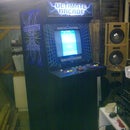
Step 6: Testing + Finished


OK, so you might be wondering "Why is only one power supply working"? Well, I only wired up one power supply to test it. The other one I didn't wire up (pots, LCD etc) except I left the input volatgs connected. The modules power LED was flashing green so I just assumed it knew it didn't have the stuff to make it work and would just keep flashing. It did - for about 20 minutes until one of the output caps blew it's rear end. Scared the Sh!t out me! So either the module doesn't like having nothing connected to it (LCD or limiting pot) or I had a unit with a reversed cap??
Either way I cleaned up the mess, soldered in a new 470uF/50V cap and tried powering it up. Nothing. It's actually dragging down the transformer voltage - So definitely faulty now! So I just ordered another one.
Just check that your controls are working the correct way around (i.e clockwise increased everything). Turn the current limit down and make sure the CC kicks in. The general purpose pots are a little sensitive, so I would recommend using either multi-turn pots or add in two pots (one coarse, one fine) if you can fit them.
I have to wait until the new module comes so I can check them working together, but the one unit working seems to be fairly accurate (reads about the same as my multimeter). I connected a load and the current seemed to be close. It will be interesting to see how they react together as a dual supply.
The LCD screens are also a little hard to read at an angle. I might put some perspex in front of the LCD if I can find something thin enough.
Normally at this stage I would start cable tie'ing everything up, however I have to wait for the new module. So I'll keep it the way it is until it arrives. Hopefully I can add a little more when it's finally finished.
Step 7: Final Thoughts & Catastrophes

Some improvements I think I would do if I made another one:
- In terms of layout, it works. Although I think I could have fit them side by side.
- May be handy to use a 3 pin IEC plug instead so you can have a virtual ground or earth
- Cut the front panel holes each time you add a layer of film. I think the holes would cut more cleanly
- Yellow, while great in principle (and limited colours in FPD) is a little hard to read
- Use 90 Deg headers and add the regulator board as a piggy back to the LCD board. It would make wiring a lot easier and free up some internal space.
- Don't forget about the power switches at the side of the case!
- Don't hook up the regulator boards with no control wiring!! Caps don't like it (apparently)
I'll add some measurements hear once the new module board comes.
I hope you find some inspiration for your own projects. If you like it and make it, put up some pictures of your incarnations.


