Introduction: DIY Motor Speed Controller With Low Voltage Cut-off


Hello everyone, thank you for stopping by. In this instructable I will show you how I made this small but powerful speed controller for DC motors that can handle upto 100 watts of power. The circuit is very simple and uses very readily available components like the very popular NE555 at it's heart.
The speed can be easily adjusted using the potentiometer and the main highlight of the project is the low voltage cut off feature which is very useful in case you want to power your project from a battery for which the voltage should not go below a specified threshold based upon your battery chemistry.
This is a fun but a useful project that I tried and don't forget to watch the demonstration at the end of this tutorial!
We have a good amount of steps to cover so let's get building!
Step 1: Gathering All the Parts for the Build


Here is a list of all the components that I have used for the project. It uses very simple and easy to obtain components some of which might already be in your inventory if you are an electronics enthusiast.
- NE 555 timer IC
- LM358 Dual OPAMP IC (you can use any other alternative opamp IC as a comparator)
- IR3205 N channel MOSFETS -2
- BC 547 transistor
- LM317 linear adjustable voltage regulator
- AMS1117 5.0V regulator (you can also use 7805 regulator)
- 1N4148 general purpose diode
- 0.1uF non polar capacitor - 2
- 0.01uF non polar capacitor -1
- 1K resistor - 3
- 10K resistor - 3
- 4.7K resistor - 1
- 100 ohm resistor - 2
- 10K preset
- 20K preset
- 100K pot
- 8 pin IC base - 2
- A small piece of protoboard or veroboard
- A case to house the components
- Soldering kit and accessories
Step 2: Marking Holes in the Veroboard for Mounting


The casing that I am using to mount the circuit board has 2 holes beneath to mount the project. So I got a permanent marker and places the board aligning it in the middle and marked the holes from the opposite side to later drill the holes. Later I will be using screws and nuts to fix the project in to the enclosure.
Step 3: Circuit Diagram for the Project

This is the entire circuit diagram of the project with the 555 timer being the man component which generate a train of PWM signals at its output which is used to control the MOSFETs. The duty cycle of the pulses can be varied from 5 percent to 95 percent using the 100K pot. This is basically the speed control of the motor. Higher the duty cycle, the MOSFETs are ON for a longer time and the speed of the motor is higher and vice versa.
The power supply to the 555 timer and the OPAMP comes from the LM317 adjustable linear voltage regulator for which I have set the output voltage to 10.5 volts which will be required to drive the gates of the MOSFET efficiently and also power up the ICs
Another feature of the project is the low voltage cut off feature which uses the LM358 OPAMP as a comparator that compares a reference voltage of 5 volts from the AMS1117 to a voltage from the 20K potentiometer. We can set the lower threshold voltage from this 20K potentiometer and after that is the input voltage falls below the threshold of 5 volts, the comparator activates which turns on the transistor BC547. This in turn pulls the reset pin of the 555 timer low and the pulse sequence stops, which deactivates the output. This feature is useful for battery powered applications.
Attachments

Step 4: Testing the Timer Circuit on Breadboard


I decided to observe the waveforms of the timer circuit on my oscilloscope and check the variation of the duty cycle. I got satisfied results with the pulse frequency of about 7 KHz and the duty cycle ranging from 5% to 95%.
Step 5: Determining the Position of the Components


It is always a good idea to roughly estimate the position of all the components so as to make sure that all the relevant components are placed close by and they can easily be connected with solder bridges and use less jumpers to make our circuit neat and tidy.
Also we must make sure that the power connections to and from the MOSFETs should be done with thick solder traces to enable it to handle large currents.
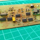
Step 6: Soldering the 555 Timer Circuitry


With the circuit diagram and the position of the components in mind, I started soldering the 555 timer section circuit and connected all the components with mostly solder bridges. After all the connections were complete, I attached the 555 timer on to the IC base. This completed my PWM signal generation section
Step 7: Adding the OPAmp Section


Next up were the components for the voltage cutoff section. I have used one of the OPAmps of the LM358 in comparator mode to enable or disable the 555 timer operation as per the input voltage status and the threshold that we have set.
Step 8: Fixing the Power Supply Section


The LM317 adjustable regulator section was next to be soldered. The output voltage was set to 10.5 volts giving the system enough voltage to power up and also drive the gate of the MOSFET efficiently. You can set the desired output by setting the 10K potentiometer accordingly.
Step 9: Adding the Power MOSFETs


The final set of components to be soldered are the MOSFET switches which will be used to regulate the output power. For my project I have used the IR 3205 MOSFETS that are rated for high current handling. You can use other MOSFETS are well or add more MOSFETs in parallel to increase the power handling capacity. One thing to make sure while adding more MOSFETs is to use a MOSFET driver circuitry to efficiently control the switching.
I have added a 100 ohm current limiting resistor and a 10K pull down resistor at the gate to discharge the gate capacitance.
Step 10: Adding the Power Wires


The last step to complete the module was to obviously add the input and the output cables for carrying the power to and from the module.
Step 11: The Module Completed..

With all the connections done, it was now time to fix the module into the enclosure using the previously drilled holes on the veroboard.
Step 12: Fixing the Module Into the Enclosure


The screws fit easily through the holes of the enclosure and the veroborad. I added some extra nut between the base of the enclosure and the veroboard to have some clearance between the base and the solder side of the veroboard to avoid false contacts. I also fixed the 100K pot through the hole provided at the front of the enclosure and secured it with the provided nut.
And with that the entire assembly was complete. The only thing left to do was to fix the top cover of the enclosure and secure it with small screws as well.
Step 13: Ready to Be Used!

The module is finally complete and works great. The MOSFETs do not heat up that much and the low voltage cut off feature works really well.
I hope you like this project and it helped you in learning something. Feel free to share this with your friends and drop your feedback and doubts in the comment section.
Also do not forget to check out the demonstration and the build process video in the next step where i also explain the working in detail. I have successfully controlled a car radiator fan that requires atleast 8 to 9 Amps to current at full speed. Don't miss out the video and while you are there consider subscribing to my channel for more such content!
Watch the video here :
Subscribe here: https://www.youtube.com/channel/UCYcjhuk6A8DWc1KB...


