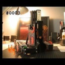
Introduction: DRILL-POWERED SPRAYPAINT CAN SHAKER
I do quite a bit of spraypainting, and as part of that, can-shaking. I wanted to make something that would ease up my life a little bit, so decided to design this simple mechanism to shake my cans for me, by means of a drill. If you haven't already guessed, this tool is a bit of a joke, as no one really needs something like this; most tools that need to be invented already have been. But, it proved to be fun, and now I have a submission for the "Build a Tool" contest. Enjoy!
ALL 3D-PRINTABLE COMPONENTS:
Supplies
Essentially everything that I used in order to build this was purchased from ServoCity:
(2m) 5mm OD Latex Surgical Tubing
(1x 2-Pack) 8mm ID 45mm L Linear Bearings
(2x 2-Packs) 1/2" ID 3/4" OD Non-Flanged Bearings
(1x 300mm) 8mm OD Steel Shafting
(1x 150mm) 8mm OD Steel Shafting
(1x 9") 1/2" OD Steel Shafting
(1x) 1/2" ID Clamp Collar
(1x) #8 x 1" Torx Screws
Step 1: BASE
MATERIAL(S):
For the base, I wanted manufacturing to be as simple as possible, so I decided on a basic rectangle for shape. The rectangle measures 24" x 4 1/4" to best fit the space the mechanism takes up. I chose pine just for its ease of manufacturing, and general strength.
Step 2: CAN CLAMP
MATERIAL(S):
(6") 5mm OD Latex Surgical Tubing
(1x 150mm) 8mm OD Steel Shafting
(1x 2-Pack) 8mm ID 45mm L Linear Bearings
(1x 2-Packs) 1/2" ID 3/4" OD Non-Flanged Bearings
(11x) #8 x 1" Torx Screws
(1x) 1KG HATCHBOX PLA 1.75mm Black
(1.5") 1/2" OD Steel Shafting
I first realized I needed a basic pivot for the spraypaint can to rest along in order to oscillate the can up and down. To attach the can to the pivot, I designed a "cradle" that clamps the can along its length using surgical tubing. A small pine board runs along the base of the cradle, connecting the second part of the pivot to the clamping cap at the end. I used a "plasticy" foam to secure the can in place while being shaken. Two linear bearings are fastened along the bottom of the pine board using two printed bearing clamps, one for the piston rod, and one for the clamping cap.
Step 3: "PISTON" COUNTERBALANCE WHEEL AND BRACKET
MATERIAL(S):
(1x 2-Pack) 1/2" ID 3/4" OD Non-Flanged Bearings
(1x) 1KG HATCHBOX PLA 1.75mm Black
(6x) #8 x 1" Torx Screws
(1x) 1/2" ID Clamp Collar
As the main component of the "piston" mechanism this design relies on to oscillate the can, I designed and manufactured a glorified wheel that rests upon a large bracket fitted with bearings. The output shaft runs out of the bracket, and through the wheel. To act as a counterbalance, I designed the wheel as more of a "cheese wedge," with the piston rod attached to the lighter end. The wheel is approximately 9" long from end to end. To fasten the output shaft to the counterbalance wheel, I screwed into the shaft through the side of the wheel, and then ground off the screwheads.
Step 4: PISTON ROD
MATERIAL(S):
(1x 300mm) 8mm OD Steel Shafting
To link the can clamp and counterbalance wheel, I designed a simple link. The link pivots on the light end of the counterbalance wheel, and attaches to a long rod that runs through a linear bearing on the can clamp. The long rod is pressed into the pivot using a pipe clamp.

Participated in the
Build a Tool Contest
14 Comments
2 years ago
I like the idea. I've been trying to come up with something to shake smaller modelling paints in dropper bottles - as they separate quite easily, and are a paint to mix by hand.
I think the design here could be improved by having the pivot point move in a similar motion that you see on old steam train wheels.
Neat idea, counterweight on the drive end is a nice touch, shows that the design hasn't been considered lightly.
Good work.
2 years ago
"No one needs this"? Well, I agree about not needing this for spray paint cans. But how about for "natural" peanut butter? If you let it sit unrefrigerated for a couple of weeks, e.g., before opening that second jar, it settles into peanut solids and peanut oil. And then you have to go through this messy stirring process -- or decant into a container and stress out your immersion blender.
I even tried jury-rigging a massage gun to shake up the jar. It worked, but was a huge pain to keep together during the shakeup process. I ought to put a little thought into a more sustainable solution...
Reply 2 years ago
Hmmm... Maybe in my next revision I will add a more versatile can clamp to allow for mulitple different variations in cylinders.
2 years ago on Step 4
Very Nice project. It seems the shaker only shakes the can up and down in the horizontal axis. I've always wanted to build a shaker that mimics what the human arm can do, it terms of shaking the can up and down along an arc path. Do you think this design could be modified to do this? Thanks!
Reply 2 years ago
I could imagine something with the can almost vertical on top of a spring, or between two springs, one above and one below the can. Strings stiff enough to make the resonant frequency similar to hand shaking, so 2-3 Hz. At the resonant frequency, even small agitations will be added up by the springs, resulting in large movement. (Think kid pushing another kid on a swing.) The paint in the can will act as a dampener, so a certain size agitator will be required. Off-center wheel under the bottom spring driven by a drill, maybe.
Reply 2 years ago
Yep. I think somewhere in the future a v2 is plausible - hopefully one that's a bit more useful... Haha!
2 years ago
What an interesting idea, but like you said what has two thumbs to shake a paint can himself? This guy! Did you test a vertical configuration? This would have the linear bearing on a pivot and the paint can attached the shaft on the cam?
Reply 2 years ago
That sounds like it would work. The whole idea of the ball in the can is to re-mix the propellant (and possibly thinning agent) with the paint. Since they separate by gravity, and the ball has to travel through the layers to assist in mixing them, shaking along the long axis while holding the can at least partially vertical, is much more efficient at mixing everything.
Reply 2 years ago
I wonder if you can make a pivot in the middle part of the can that would allow the can to whirl around and up and down allowing the bearing inside to traverse from tip to bottom. It has potential - your project caught my eye and got my vote.
Reply 2 years ago
This could be really interesting since the distance on the cam between the cam pivot and the can and also between the drill and the end of the cam you could add a belt system that could coordinate flipping the can in time with the cam cycling. That could be really fun.
Reply 2 years ago
Brilliant! And if the can escapes, we'd have a flying but very well shaken can!
Reply 2 years ago
Not a bad idea! Y'know, this may actually become useful...
2 years ago on Introduction
Sorry, aber das gehört zu den Dingen, die die Welt nicht braucht.
Nichtsdestotrotz: schön gebaut.
Reply 2 years ago