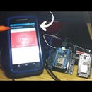
Introduction: ESP8266/ESP12 Witty Cloud - Arduino Powered SmartThings RGB Controller
RGB's RGB's RGB's Everywhere! Who doesn't like having some cool looking colorized lighting around their home these days? This little project shows off the ESP8266 mixed with SmartThings control and winds up as a real neat RGB controller for LED strips and the like. A Gizwits ESP8266 Witty Cloud controller is used for convenience sake thanks to its integrated RGB LED, but most any ESP8266 ESP12/ESP32 should work. I'm sure you have a couple...OR 10 laying around to try this out. Go build one and HAVE FUN!
Step 1: Hardware - What You'll Need - EASY ONE THIS TIME!
I DO NOT endorse, represent, or receive anything at all for the examples below. Caveat Emptor.
Substitute as needed for your individual requirements/parameters. Links to products are only for examples and not promotion.
1. ESP8266 GizWits Witty Cloud MC
2. Samsung SmartThings 2.0 Hub
Step 2: Software - What You'll Need
ASSUMPTIONS: Comfortable working with Arduino IDE, Libraries, SmartThings IDE and GITHub.
Step 3: Hardware Setup
- Carefully position your USB cable so it's termination shape matches that of the connection on your ESP8266. Kind of like a 1 piece puzzle.
- Using gentle force, slowly seat the cable's connector into the connector of the ESP.
- Plug other end of USB cable into the USB port of the device you will be using to program/power your ESP.
- Yes...these steps are purposely sounding sarcastic. I hope you've enjoyed and are not annoyed!
Step 4: Software Setup
ASSUMPTIONS: Comfortable working with Arduino IDE, Libraries, SmartThings IDE and GITHub.
- Login to your respective SmartThings IDE and GITHub accounts.
- Follow ALL steps shown here by Daniel Ogorchock. AKA Ogiewon.
I know there is a lot of initial information and configuration if this is your first time setting up the ST_Anything configurations, but it is worth it. PLEASE feel free to ask any questions you may have along the way. In addition, this SmartThings Forum for this project is a GREAT place for tips and advice.
Modify the attached Arduino sketch, adding your WiFi/SmartThings environment specifics. The sketch calls out where to make the changes, as do the steps on the GITHub Page.
NOTE: The default pins used in the sketch provided in the Repo are specific to the standard ESP8266 ESP12. To work on the the Witty ESP8266 as described in this Instructable, please change the PIN_RGB1_Red pin from D5 to D8, and also uncomment the pin definition #define D8 15. See ScreenShot.


