Introduction: Embedded Programming (Complete Tutorial for Programming Your PCB)
Embedded programming plays a vital role in the modern world, powering a wide range of devices and systems that we rely on daily. From smartphones and home appliances to automotive systems and industrial machinery, embedded programming enables the functionality and intelligence of these devices. In this introduction, we will explore the importance of embedded programming and its impact on various industries and sectors.
1. Enabling Device Functionality:
Embedded programming is the backbone of device functionality. It involves writing software that runs directly on microcontrollers or microprocessors embedded within electronic devices. By programming these devices, developers can control hardware peripherals, process data, implement algorithms, and enable the desired features and capabilities of the device.
2. Optimizing Performance and Efficiency:
Embedded programming allows developers to optimize the performance and efficiency of devices. By writing efficient code, utilizing hardware resources effectively, and implementing optimized algorithms, embedded programmers can ensure that devices operate reliably, respond quickly, and consume minimal power. This is particularly crucial for battery-powered devices and systems with limited resources.
3. Real-Time and Safety-Critical Systems:
Embedded programming is essential for real-time and safety-critical systems. These systems require precise and timely responses to external events and must adhere to strict safety standards. Examples include medical devices, automotive systems, aerospace applications, and industrial control systems. Embedded programmers develop code that meets real-time constraints, ensures system stability, and incorporates safety measures to protect users and equipment.
4. Internet of Things (IoT) Connectivity:
The rise of the Internet of Things (IoT) has further emphasized the importance of embedded programming. IoT devices are interconnected and communicate with each other and the cloud. Embedded programmers develop the software that enables IoT devices to gather and transmit data, interact with other devices, and provide intelligent functionality. This connectivity drives innovation and efficiency in various domains, such as smart homes, industrial automation, healthcare, and agriculture.
5. Firmware Updates and Maintenance:
Embedded programming enables firmware updates and maintenance of devices throughout their lifecycle. Firmware updates provide bug fixes, security patches, and feature enhancements, ensuring that devices remain up-to-date and secure. Embedded programmers develop update mechanisms and implement robust firmware management practices to facilitate seamless updates and maintenance.
6. Customization and Innovation:
Embedded programming allows for customization and innovation in device design. By developing custom software, developers can tailor devices to specific requirements and differentiate their products in the market. Embedded programming empowers creativity and innovation by enabling the implementation of unique features, user interfaces, and functionality that meet specific user needs.
7. Integration and System-Level Design:
Embedded programming facilitates the integration and system-level design of complex devices and systems. Developers can coordinate the interaction between multiple components, sensors, actuators, and communication protocols. They create software architectures that enable seamless collaboration between different subsystems, ensuring smooth operation and data flow.
In conclusion, embedded programming is of utmost importance in today's interconnected and technology-driven world. It enables device functionality, optimizes performance and efficiency, supports real-time and safety-critical systems, drives IoT connectivity, enables firmware updates, fosters customization and innovation, and facilitates system-level design. By mastering embedded programming, developers unlock a world of possibilities and contribute to the advancement of technology across various industries and sectors.
Supplies
I have used the Circuit HERE if you want to check how I made it
Step 1: Understanding Microcontroller(ATTINY44)
Beginning with the AVR
Microcontrollers are used in many embedded systems applications, let’s look at some consumer products like air conditioners, the brain is a microcontroller that is responsible for receiving sensor data like a temperature sensor that senses the current room temperature, turning that input into a series of commands to go to the air conditioner compressor to work or not. Or even the microcontroller in your universal remote control translates your key presses into a precise series of pulses for an infrared LED that tells the microcontroller inside your television to change the channel or increase the volume.
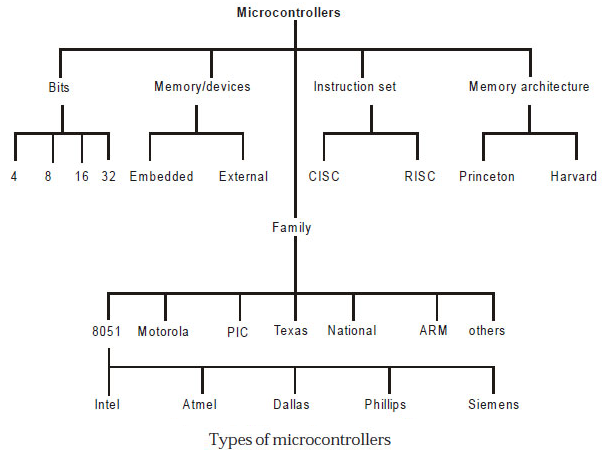
- When it comes to choosing your microcontroller, There are many options out there. There are so many microcontroller families available. Those are 8051, PIC, AVR, ARM, etc. Each microcontroller family has its specifications like the processor speed, flash memory size, RAM size, ...etc.

Here's what's inside the ATTiny44:
Flash (program memory)4096 bytesRAM256 bytesEEPROM256 bytesGPIO Pins8 + RST + XTAL1 + XTAL2ADC Channels8PWM Channels4Clock optionsInternal 1/8mhz, an external crystal or clock* up to 20mhzIn order to make use of the GPIO pins, we must understand the architecture first. I found this tutorial very useful, and I'll be quoting and editing the next paragraph, to suit the ATTiny44.
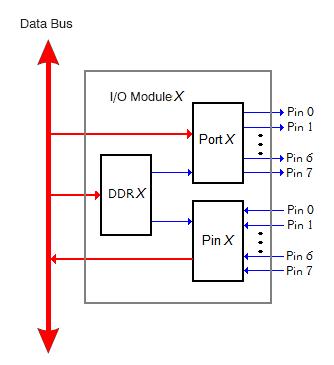
Atmel AVR is an 8-bit microcontroller. All its ports are 8-bit wide. Every port has 3 registers associated with it each one with 8 bits. Every bit in those registers configures the pins of a particular port. Bit0 of these registers is associated with Pin0 of the port, Bit1 of these registers is associated with Pin1 of the port, …. and likewise for other bits. These three registers are as follows : (x can be replaced by A, B, C, D as per the AVR you are using)
DDRx register
PORTx register
PINx register
- DDRx register
- DDRx (Data Direction Register) configures the data direction of port pins. This means its setting determines whether port pins will be used for input or output. Writing 0 to a bit in DDRx makes the corresponding port pin as input while writing 1 to a bit in DDRx makes the corresponding port pin output. Example: to make lower nibble(half byte) of port B as output and higher nibble(half byte) as input : DDRB = 0b00001111;
- PINx register
- PINx (Port IN) is used to read data from port pins. To read the data from the port pin, first, you have to change the port’s data direction to input. This is done by setting bits in DDRx to zero. If the port is made output, then reading the PINx register will give you data that has been output on port pins.
- PORTx register
- PORTx is used for two purposes:
- To output data: when the port is configured as output
- When you set bits in DDRx to 1, the corresponding pins become output pins. Now you can write data into respective bits in the PORTx register. This will immediately change the state of output pins according to the data you have written. Example: PORTB = 0xFF; will write HIGH on every pin that was set as output.
- To activate/deactivate pull-up resistors – when the port is configured as input
- When you set bits in DDRx to 0, i.e. make port pins as inputs, then corresponding bits in the PORTx register are used to activate/deactivate pull-up registers associated with that pin. To activate the pull-up resister, set the bit in PORTx to 1, and to deactivate (i.e. to make port pin tri-stated) set it to 0.
- We can visualize the relation between the DDR, PIN, and PORT like the following:
I'll be trying to program a simple task; which is switching an LED ON and OFF when the button is pressed. I made a flow chart of the sequence:
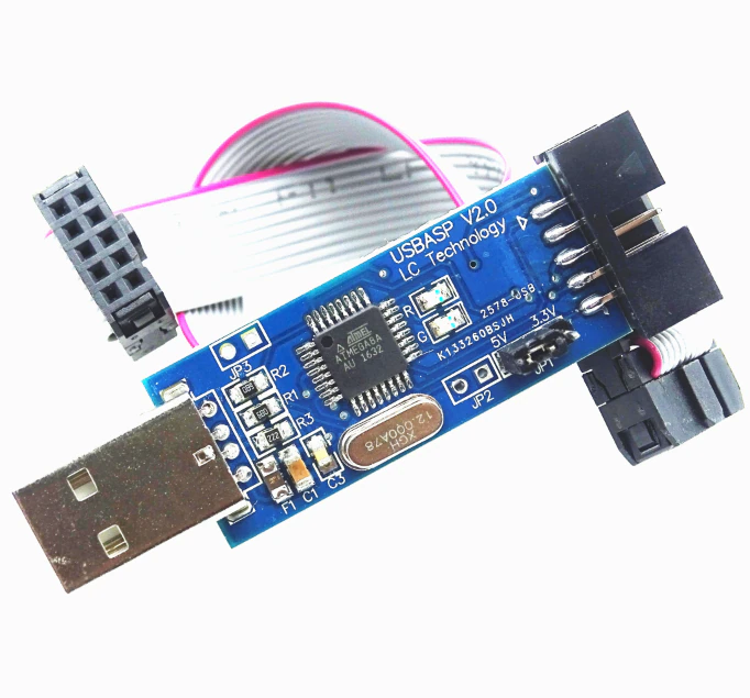
I will Upoad the codes using ASP Programmer
Step 2: ARDUINO CODE
The Arduino code is pretty straightforward. You don't need to remember which DDR, PIN, or PORT. You just set the pinMode in the void setup() section, which will be executed once, then write your code sequence in the void loop() section and it will run repeatedly. Here are some quotes about the most important functions in the Arduino-C language.
- pinMode
- Configures the specified pin to behave either as an INPUT or an OUTPUT. It is possible to enable the internal pullup resistors with the mode INPUT_PULLUP. Additionally, the INPUT mode explicitly disables the internal pullups.
- Syntax: pinMode(pin, state)
- digitalWrite
- Write a HIGH or a LOW value to a digital pin.
- Syntax: digitalWrite(pin, value)
- digitalRead
- Reads the value from a specified digital pin, either HIGH or LOW.
- Syntax: digitalRead(pin)
- delay
- Pauses the program for the amount of time (in milliseconds) specified as the parameter. (There are 1000 milliseconds in a second.)
- Syntax: delay(ms)
The Logic of the code is too simple, All I made is to make the lamps turn on and turn off every period of time I started to make a simple version of the code to test the pins and the function of the code
  int Led1 = 10

void setu() {
  pinMode (Led1 ,OUTPUT);
  digitalWrite (Led1 , HIGH);
}

void loop () {

  digitalWrite(Led1, HIGH);
  delay(1000);
  digitalWrite(Led1 , LOW);
  delay(1000);


}
After I made sure of the logic and the pins, I began to write the complete code
int Led2 = 10;
int Led1 = 9;
int Led3 = 2;
int Led4 = 8;
int Led5 = 3;
int Pushbutton = 7;
 void setup() {

  pinMode (Led1 , OUTPUT);
  pinMode (Led2 , OUTPUT);
  pinMode (Led3 , OUTPUT);
  pinMode (Led4 , OUTPUT);
  pinMode (Led5 , OUTPUT);
  pinMode (Pushbutton , INPUT);
  digitalWrite(Led1 , LOW);
  digitalWrite(Led2 , LOW);
  digitalWrite(Led3 , LOW);
  digitalWrite(Led4 , LOW);
  digitalWrite(Led5 , LOW);
    digitalWrite(Led5 , LOW);
    digitalWrite(Pushbutton , 1);

}

void loop() {
digitalWrite(Led1 , HIGH);
  delay (300);
  digitalWrite(Led2 , HIGH);
  delay (300);
  digitalWrite(Led3 , HIGH);
  delay (300);
  digitalWrite(Led4 , HIGH);
  delay (300);
  digitalWrite(Led5 , HIGH);
  delay (300);
  digitalWrite(Pushbutton , HIGH);
  delay (300);
  digitalWrite(Led1 , LOW);
  digitalWrite(Led2 , LOW);
  digitalWrite(Led3 , LOW);
  digitalWrite(Led4 , LOW);
  digitalWrite(Led5 , LOW);
  delay (300);
/*  ------------------- */
  digitalWrite(Led1 , HIGH);
  delay (250);
  digitalWrite(Led2 , HIGH);
  delay (250);
  digitalWrite(Led3 , HIGH);
  delay (250);
  digitalWrite(Led4 , HIGH);
  delay (250);
  digitalWrite(Led5 , HIGH);
  delay (250);
  digitalWrite(Pushbutton , HIGH);
  delay (250);
  digitalWrite(Led1 , LOW);
  digitalWrite(Led2 , LOW);
  digitalWrite(Led3 , LOW);
  digitalWrite(Led4 , LOW);
  digitalWrite(Led5 , LOW);
  delay (250);
  /*------------------ */
  digitalWrite(Led1 , HIGH);
  delay (200);
  digitalWrite(Led2 , HIGH);
  delay (200);
  digitalWrite(Led3 , HIGH);
  delay (200);
  digitalWrite(Led4 , HIGH);
  delay (200);
  digitalWrite(Led5 , HIGH);
  delay (200);
  digitalWrite(Pushbutton , HIGH);
  delay (200);
  digitalWrite(Led1 , LOW);
  digitalWrite(Led2 , LOW);
  digitalWrite(Led3 , LOW);
  digitalWrite(Led4 , LOW);
  digitalWrite(Led5 , LOW);
  delay (200);
  /*--------------- */
  digitalWrite(Led1 , HIGH);
  delay (150);
  digitalWrite(Led2 , HIGH);
  delay (150);
  digitalWrite(Led3 , HIGH);
  delay (150);
  digitalWrite(Led4 , HIGH);
  delay (150);
  digitalWrite(Led5 , HIGH);
  delay (150);
  digitalWrite(Pushbutton , HIGH);
  delay (150);
  digitalWrite(Led1 , LOW);
  digitalWrite(Led2 , LOW);
  digitalWrite(Led3 , LOW);
  digitalWrite(Led4 , LOW);
  digitalWrite(Led5 , LOW);
  delay (150);
  /*------------*/
  digitalWrite(Led1 , HIGH);
  delay (100);
  digitalWrite(Led2 , HIGH);
  delay (100);
  digitalWrite(Led3 , HIGH);
  delay (100);
  digitalWrite(Led4 , HIGH);
  delay (100);
  digitalWrite(Led5 , HIGH);
  delay (100);
  digitalWrite(Pushbutton , HIGH);
  delay (100);
  digitalWrite(Led1 , LOW);
  digitalWrite(Led2 , LOW);
  digitalWrite(Led3 , LOW);
  digitalWrite(Led4 , LOW);
  digitalWrite(Led5 , LOW);
  delay (100);
  /* ----------------- */
    digitalWrite(Led1 , HIGH);
  delay (50);
  digitalWrite(Led2 , HIGH);
  delay (50);
  digitalWrite(Led3 , HIGH);
  delay (50);
  digitalWrite(Led4 , HIGH);
  delay (50);
  digitalWrite(Led5 , HIGH);
  delay (50);
  digitalWrite(Pushbutton , HIGH);
  delay (50);
  digitalWrite(Led1 , LOW);
  digitalWrite(Led2 , LOW);
  digitalWrite(Led3 , LOW);
  digitalWrite(Led4 , LOW);
  digitalWrite(Led5 , LOW);
  delay (50);
}
The Logic of the code is too simple, All I made is to make the lamps turn on and turn off every period of time I started to make a simple version of the code to test the pins and the function of the code
Step 3: AVR-C Code
The AVR-C code would be very similar to the previous code, except for it would be more detailed. It's needed to define everything related to the DDR, PIN, and PORT.
- It begins by defining the clock speed
- #define F_CPU 20000000UL
- Then include the default libraries for the AVR MCUs and for timing
- #include <avr/io.h>
- #include <util/delay.h>
- The next thing to do is to define the int main(void) function, which will be executed directly when the MCU is powered. Inside this function, we can write any sequence we want for the code. The code written inside the main is executed only for one time.
- The DDRB = 0b00000100; line, will configure Pin 2 at Port B as Output.
- The PORTA = 0b10000000; line, will pull up Pin 7 at Port A.
- This part of the code is similar to the code written in the void setup() function in the Arduino-C code.
- Since the main code is only executed once, we need to nest our repeating sequence in a loop. This is done by using while(1) infinite loop, where we can nest the condition and the ON/OFF sequence.
- The condition is simple: if (!(PINA & (0b10000000))). The PINA reads the whole pins byte (A). To read a specific pin, we should just ignore the rest of the pins by anding them with zeros. When the required pin is connected to GND the expression result will be! (0) which is 1, and vice versa.
- Now, we can just use PORTB |= 0b00000100; to output logic 1 on Pin 2 at Port B; leaving the other pins in whatever state. This is because (0) | 0 = 0 and (1) || 0 = 1
- and PORTB &= 0b11111011; outputs logic 0 on Pin 2 at Port B, leaving the other pins in whatever state, because (0) & 1 = 0 and (1) & 1 = 1
After turning On or Off the output pin, we need a delay to see the effect. This is done by using _delay_ms(1250); , which is similar to the delay(ms) function in the Arduino-C.
and here's the full code:
#define F_CPU 20000000UL
#include <avr/io.h>
#include <util/delay.h>

int main(void)
{
    DDRB   = 0b00001100;      //Configured Pin 2 at Port B as Output
    PORTA  = 0b10000000;      //Pull-up Pin 7 at Port A.
    while (1)
    {
        if (!(PINA & (0b10000000)))
        {
            // Output logic 1 on Pin 2 at Port B
            PORTB |= 0b00001100;

            _delay_ms(1250);

            // Output logic 0 on Pin 2 at Port B
            PORTB &= 0b11110011;

            _delay_ms(1250);
        }
    }
}


![Tim's Mechanical Spider Leg [LU9685-20CU]](https://content.instructables.com/FFB/5R4I/LVKZ6G6R/FFB5R4ILVKZ6G6R.png?auto=webp&crop=1.2%3A1&frame=1&width=306)


