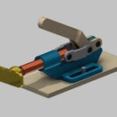
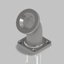
Introduction: Getting Started With Autodesk Inventor (Basics and User Interface)
Upon successful completion of this lesson, you will be able to:
- Describe the key characteristics of feature-based, parametric solid modelling
- Identify various commands using Inventor's ribbon interface
- Navigate Inventor's 3D and 2D environments
- Explain how different dimensioning styles convey design intent
Attachments
Supplies
- PC that meets the minimum requirements of the software
- Autodesk Inventor Professional
- Training Files as attached to this Instructable
Step 1: What Is Autodesk Inventor?
Autodesk Inventor is a computer-aided design (CAD) application for 3D mechanical design, simulation, visualization, and documentation.
Inventor allows 2D and 3D data integration in a single environment, creating a virtual representation of the final product that enables users to validate the form, fit, and function of the product before it is ever built. This can be referred to as Digital Prototyping. Autodesk Inventor includes powerful parametric, direct edit and freeform modelling tools.
Check out some of the interesting ways the software is being used: https://www.autodesk.com/customer-stories/case-studies?products=product--inventor
Step 2: Parametric Modelling With Autodesk Inventor
There are several styles of modelling that may be used in Autodesk Inventor; however, this series will focus on Parametric Modelling.
What is Parametric Modelling
Parametric Modelling is the creation of digital models using rules in the form of constraints or parameters. When properly applied, these rules will ensure that the model reacts to revision in the appropriate manner. Parametric Modelling allows the designer to build intelligence into their model(s). This allows the model(s) to be updated or revised quickly and accurately - removing room for error and increasing efficiencies through prompt response to change requests.
Example:
You manufacture fasteners. You would like to develop a part family of customized bolts. The following parameters have been developed for implementation:
Constant Parameters:
- Thread form
- Hexagonal head size and style
- Unthreaded shoulder length
Driven/Variable Parameters:
- Bolt overall length
Using these rules, we can develop a base model with the parameters mentioned above. With the parameters properly in place, we are able to adjust the variable or "key" parameters to achieve a perfectly accurate change that complies with the specified rules. Check out the attached image for a visual representation of the part family.
Step 3: Step 1 - Autodesk Inventor User Interface (UI)
Start with these steps:
- Open Autodesk Inventor Professional
- Download and extract the Training Files attached to this Instructable
- Open "UI Demo File.ipt"
Autodesk Inventor utilizes a ribbon-style interface, similar to many popular Microsoft products.
As seen in the UI image, there are several standard areas available in Autodesk Inventor's UI. These will be called upon throughout the series so it is good to become familiar with them. Try to locate each area with the UI Demo File open. Once you feel comfortable, move to the next step.
Step 4: Step 2 - Navigating the Model Space
We typically utilize two environments within .ipt (part) files - 2 dimensional (2D) and 3 dimensional (3D) environments.
2D Environments:
Most of the part models we will develop, begin with 2D sketches. These sketches provide us with the profiles and geometry we will need to develop 3D features. In the 2D space, we are able to work infinitely in two axes; however, we may still rotate and zoom infinitely in all axes.
3D Environments:
The 3D environment is where we will perform feature creation. Typically, feature creation begins with a 2D sketched profile. It is important to remember that you can work and move infinitely in all directions.
Graphical User Interface (GUI) Manipulation
If desired, refer to the attached video for more information on completing the steps below
- Open "UI Demo File.ipt"
- Notice the View Cube in the top right corner of the Graphics Window
- Experiment with the different views you are able to achieve using the View Cube.
- Left Click and drag the View Cube to Orbit within the environment
- You may Right Click on the View Cube a redefine Front, Top and Home views if required
- The centre mouse wheel is also very powerful when manipulating the environment
- Scrolling the centre mouse wheel will zoom in and out to the mouse pointer
- Holding down the centre mouse wheel and dragging will pan the model in 2D
- Holding the Shift key and the centre mouse wheel will Orbit the model as you drag (This is very useful in 3D)
- Double-clicking the centre mouse wheel will Zoom Extents - displaying all entities centred in the Graphics Window
- You may also access these commands on the vertical right-hand side of the Graphics Window
- In addition to the aforementioned commands, you will also find "Look At". Look At allows you to position your view normal to a planar face as selected
- You will also find additional Zooming commands in this area - experiment with them!


