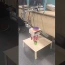
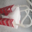
Introduction: Gripper Made of Soft Muscles With Arduino Code
In my previous tutorial I told you guys how to make the soft gripper, in this tutorial I will explain how we can bring that gripper in to action to perform some practical tasks, this tutorial includes the circuitry and arduino code.
so those who haven't watched my previous tutorial are highly recommended to watch it before they move forward.
Following things are required for our project, I will link the sites from where you can order these things.
Step 1: Gripper
In my previous tutorial i made this, so if you want to move forward in this project then you should visit that tutorial first.
Step 2: Arduino Mega (Arduino Uno Recommended)
Step 3: L298N Motor Drive Controller
Step 4: Hydraulic Air Pump
Step 5: Solenoid Valve
Step 6: Silicone Pipe
Step 7: Silicone Tube Connector
Step 8: Wires
Step 9: 12 V Lithium Battery
Step 10: Soldering Machine
Step 11: Soldering Wire
Step 12: Links:
- Gripper
- L298N Motor Drive Controller
- Hydraulic Pump
- Solenoid Valve
- Silicone Pipes
- Silicone tube connector
- Wires
- 12 V Lithium Battery
- Soldering Machine
- Soldering Wire
These are all for reference.
Now I will explain the circuitry and arduino code
Step 13: Solder the Wires With the Solenoid Valve
Step 14: Pump Testing
Test the pump simply by connecting its two end with the OUT 1 and OUT 2 of the motor river, connect the 12 V and ground of the driver with the 12 V battery. Now connect the 5V of the driver with the ENA pin of the driver, connect other end of the ENA pin with the IN 1 or IN 2 as shown in the figure. You will see that pump will start working.
Step 15: Valve Testing
Valve testing is much more easier than pump testing, simply attach the two ends of the soldered valve with the 12 V battery, if it gives you CLICK like sound it means that it is working properly.
Step 16: Circuit Making
Before explaining the circuity i would like to add that in the motor driver, OUT 1 and OUT 2 are controlled with the help of three pins ENA, IN 1 and IN 2 and same is the case with OUT 3 and OUT 4.
Now take the motor driver and arduino and perform the following tasks.
- Attach two ends of the pump with the OUT 1 and OUT 2 of the driver.
- Attach two ends of the soldered valve with the OUT 3 and OUT 4 of the driver.
- Attach 12 V and GND of the driver with the 12 V Lithium Battery.
- Attach 5 V pin of the driver with the ENA and attach other end of the ENA pin with ENB pin through wire (make sure to make the diagonal connection i-e lower pi of ENA with upper pin of ENB) of the driver.
- Attach the IN 1 and IN 4 with the 2 and 3 pin of the arduino as shown in the figure.
- Attach the ground of the arduino with the ground terminal of the 12 V battery.
NOTE: ENA and ENB of the driver can be controlled through arduino but in this tutorial i have simply connected them with the 5 V of the driver.
Step 17: Connection Between Gripper, Pump and Valve
Take three-way silicone connector and attach one end with the gripper and other two ends with the pump and valve respectively, as shown in the figure.
WORKING:
The purpose of the pump is two inflate the gripper but its really inconvenientif i have to release the air from the gripper manually, so to avoid that i have used valve. During inflation the valve will remain close and when we want to release the air from the gripper we can simply use the valve for that purpose.
Step 18: Simple Testing Code and How It Works
void setup() {
  // put your setup code here, to run once:
  pinMode(2,OUTPUT);
  pinMode(3,OUTPUT);
}
void loop() {
  // put your main code here, to run repeatedly:
  digitalWrite(2,HIGH);
  digitalWrite(3,LOW);
  delay(1500);
  digitalWrite(2,LOW);
  digitalWrite(3,HIGH);
  delay(1500);
}
so this is the simplest code that we can use for this system to work,
- In setup we simply defines the pin mode and set it to OUTPUT. Here 2 and 3 pin refers to the connection of pump and valve respectively with arduino.
- we want the pump to fill some air in the gripper and during that time we want valve to be closed so for that we kept the pin 2 of pump HIGH and pin 3 of valve LOW.
- we added the delay for 1.5 sec so during this time the gripper will get inflate.
- Now we want to remove all the air from the gripper so for that we toggle the states of the pins (2 pin of pump to LOW and 3 pin of the valve to HIGH), this will remove all the air from the gripper during 1.5 sec (delay of 1.5 sec) and will come back to its initial state
If you have successfully reached to this step than congratulation....!!!
Step 19: Final Look
In the uploaded video i haven't use the valve, but i have tasted it with vlave and it works fine.
In the next tutorial i will move this gripper in a 3 dimensional space using three linear motors.


