Introduction: HAVE FUN WITH BICOLOR MATRIX 32x32
Today I will share following topics base on a bicolor matrix led 32x32:
- D.I.Y a bicolor led matrix 32x32.
- How to control led board above with NodeMCU ESP8266 via B.A.M method.
- Introduce and share my code for some cool real time clock projects with this bicolor led board.
Let's start with some videos:
- Rainbow letters and images: is controlled by NODEMCU.
- Handwritten Clock Version 2:
- Tetris clock: is referenced from TobiasB48
- Handwritten Clock Version 1:
- Morphing Digital Clock: is referenced from HariFun.
Step 1: MATERIAL LIST
Main components include:
- 1pcs x Arduino Mega 2560. (Optional)
- 16pcs x 0.1uF Capacitors.
- 200pcs x R100.
- 20pcs x R1K.
- 40pcs x R10K.
- Some wires, acrylic plate.
- Power supply 5V, 10A. (I used a power supply 5V-40A for this project)
Step 2: SCHEMATIC
This is the circuit diagram of the whole project; it is a quite big file and you can download high resolution PDF file HERE. With this overall schematic, we will easily understand how to scan rows and columns for led matrices, as well as, how to apply the 4-bit BAM method during row and column scanning.
On the circuit diagram, I separated 32x32 = 1024 red and 32x32 = 1024 green LEDs in groups and connect default matrix pin in Fritzing to rows and columns buses. You have to connect color pins properly according to the specifications after purchasing bicolor led matrix.
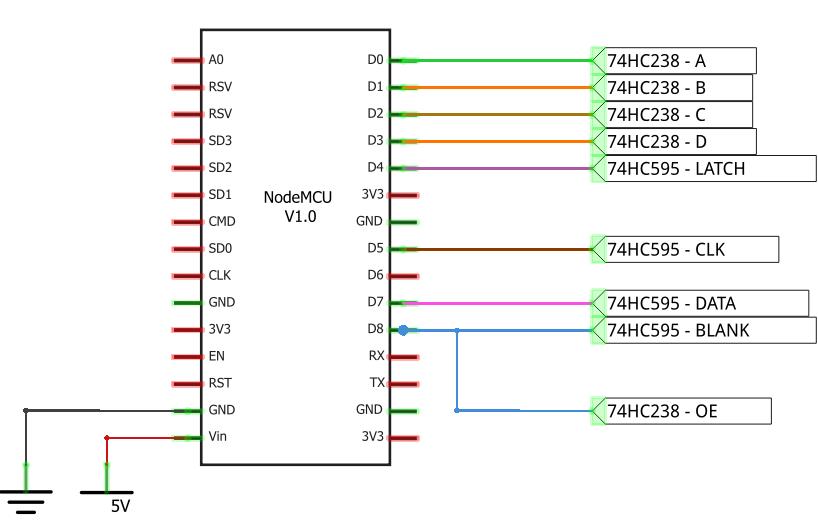
NODECU pins are used as below:
// PINS USING ON NODEMCU
#define blank_pin	D8  // BLANK PIN - 74HC595
#define latch_pin	D4  // LATCH PIN - 74HC595
#define clock_pin	D5  // CLOCK PIN - 74HC595
#define data_pin	D7  // DATA PIN - 74HC595

#define RowA_Pin	D0  // A PIN - 74HC238
#define RowB_Pin	D1  // B PIN - 74HC238
#define RowC_Pin	D2  // C PIN - 74HC238
#define RowD_Pin	D3  // D PIN - 74HC238
//#define OE_Pin	D8  // ENABLE OUTPUT PIN - 74HC238 (Connect to blank_pin).
Note that:
- I used 5 signals to control 2x74HC238 for implementing one 4 to 16 decoder. Then these 16 outputs will control 32 rows of bicolor led matrix through PNP and NPN transistors. In other words, my led panel have 1/16 scan rate, so only one row of 16 is on at a time. You can see how scan pattern a 32x32 led board with scan rate 1/16 looks like, at this link: https://www.sparkfun.com/sparkx/blog/2650
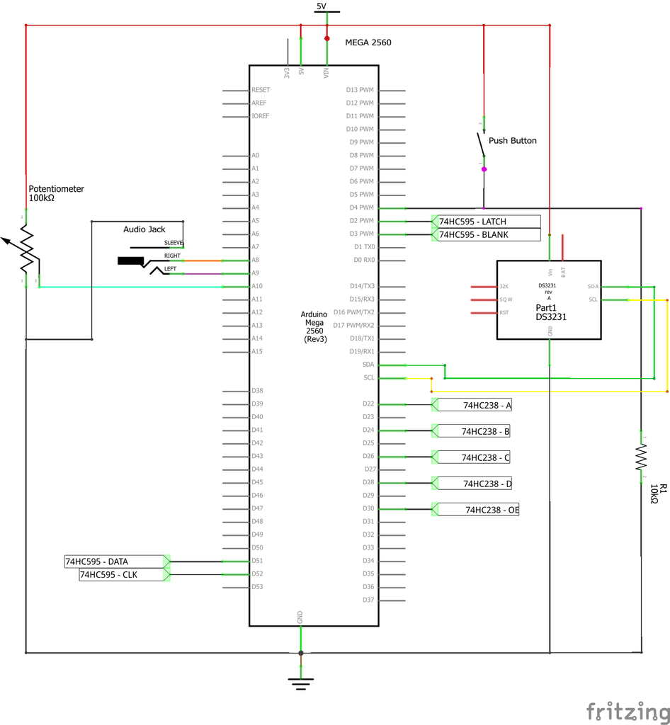
- OE PIN - 74HC238 and BLANK PIN - 74HC595 are both connect to NODEMCU - D8 pin. This is an important key to minimize flickering and noise because we only enable the OE pin (Output Enable) for 74HC595 (columns) and 74HC238 (rows) when we needed. I have also tested this Led board on Arduino Mega 2560 with 2 OE signals which are individually controlled, one for 74HC595 and the remaining signal for 74HC238. It also gave good results. Check detail at STEP 5.
Step 3: PCB BOARD DESIGN AND ETCHING
You can download as attached links for following schematics and PCB files:
1. Row scanning circuit schematic and Eagle PCB real size.
2. Column scanning circuit schematic and Eagle PCB real size.
3. Led matrix board 32x32 schematic and Eagle PCB real size for 16x32 led board.
I etched myself these printed circuit boards at home by Toner Transfer Method and concentrated ferrous chloride. The pictures below are the results that I did:
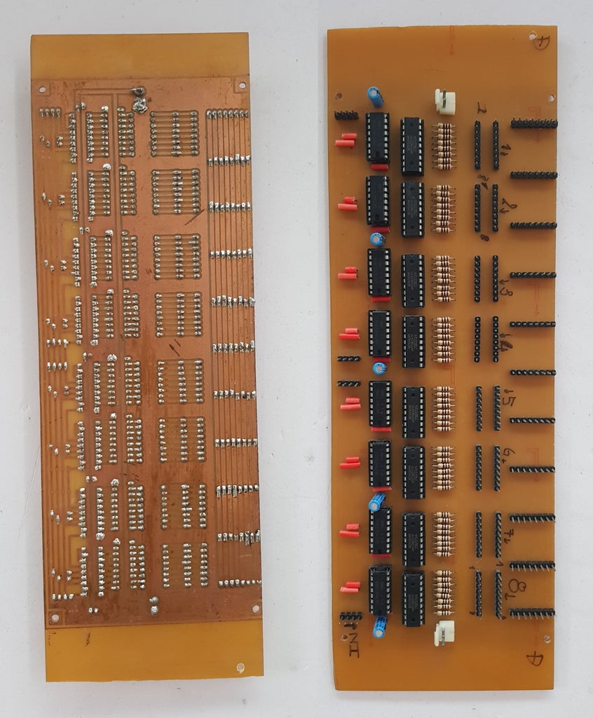
- Column Scanning Board: we need 2 sets of column scanning PCB for RED and GREEN color.
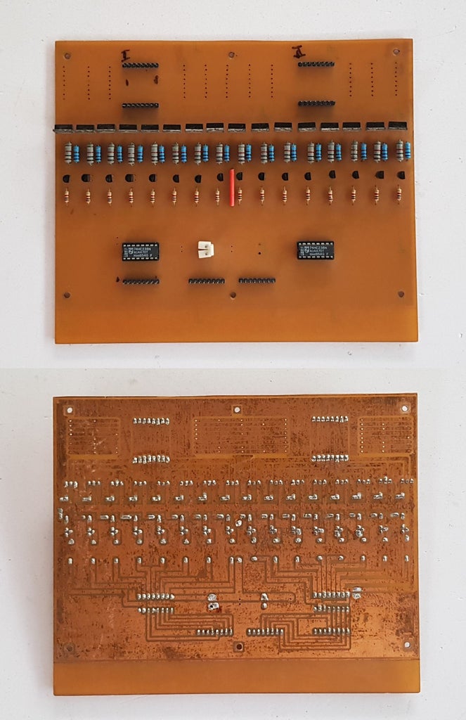
- Row Scanning Board
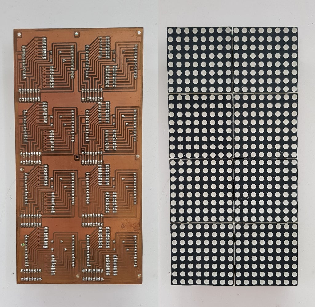
- Led Matrix 16x32 Board: Combine 2 sets of led board 16x32 PCB to become Led Board 32x32.
Step 4: ASSEMBLY WORK
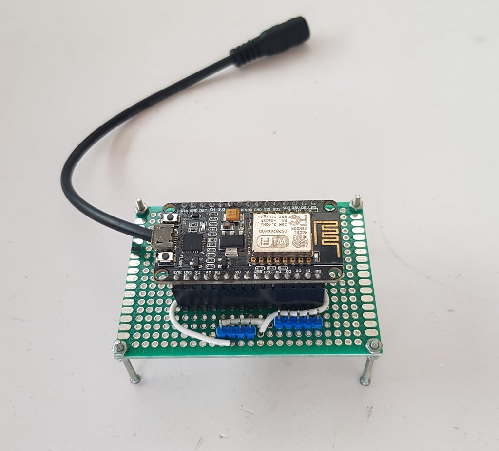
- Soldering female header and NodeMCU output pins on Double Sided Printed Prototyping Board. For power supply, I connected 5V to Vin pin of NODEMCU. And NODECU pins are used as described on STEP 2.
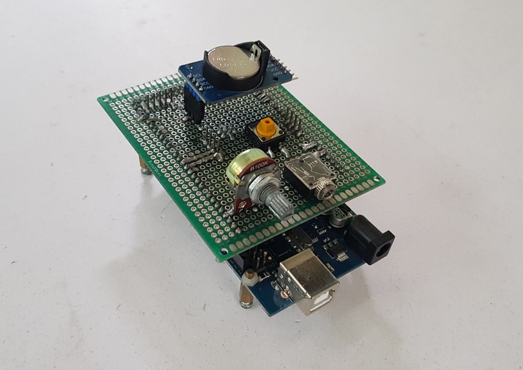
- I also soldered one more circuit for Arduino Mega 2560 to test this Led Panel, with DS3231 (SDA - SCL), one potentiometer (A10), one push button (D4) and one audio jack (Right A8 - Left A9).
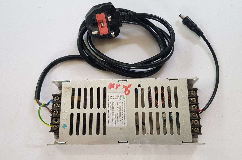
- Prepared the 5V power supply
- Connecting PCB boards and NODEMCU all together following the schematic on STEP 2. Putting all PCBs, nodeMCU and Led Board into box.

- It's ready for programming.
Step 5: PROGRAMMING
Controlling 32x32 bicolor led table with NODEMCU, 16x74HC595 and 2x74HC238 is not easy. Because NodeMCU has limited inputs/ output pins, and timing calibration works also caused many difficulties. I have tested and dealed with noise and flickering issues many times. But in the end, I minimized these problems and my result was amazing!!!
In this project, I used Timer 1 in NODEMCU and a callback routine to implement B.A.M process.
timer1_isr_init();				// Initializes the timer 1.

timer1_attachInterrupt(timer1_ISR);		// Attach the interrupt service routine (timer1_ISR).

timer1_enable(TIM_DIV16, TIM_EDGE, TIM_SINGLE);	// Setup and enable timer 1.

timer1_write(60);				// Tell timer 1 to call the timer1_ISR after 60 clock cycles.
The reason I used Timer 1 instead of Timer 0 or Ticker standard library because:
- Timer 0 has been used for WiFi Functions.
- Ticker can't call an interrupt functions in microseconds. (in my case: 12us). You can see Ticker standard library at: https://github.com/esp8266/Arduino/tree/master/li...
The table below describes the Timer 1 and B.A.M settings as well as their relationship. With this setup, our timer clock runs at 5MHz (80MHz/16=5MHz) or 1/5MHz = 0.2us. When we set timer1_write (60), this means the interrupt will be called every 60 x 0.2us = 12us and B.A.M process need about 8 Ticks x 12us = 96us to set the "Least Significant Bit of BAM_Bit" to "ON" or "OFF", which gives a multiplex frequency of about 10.4 kHz.
Note: This explanation base on 8 Ticks elapsed time on the lowest bit weight of BAM_Bit. You can check detail at item "main attach interrupt service routine" for my final setting.
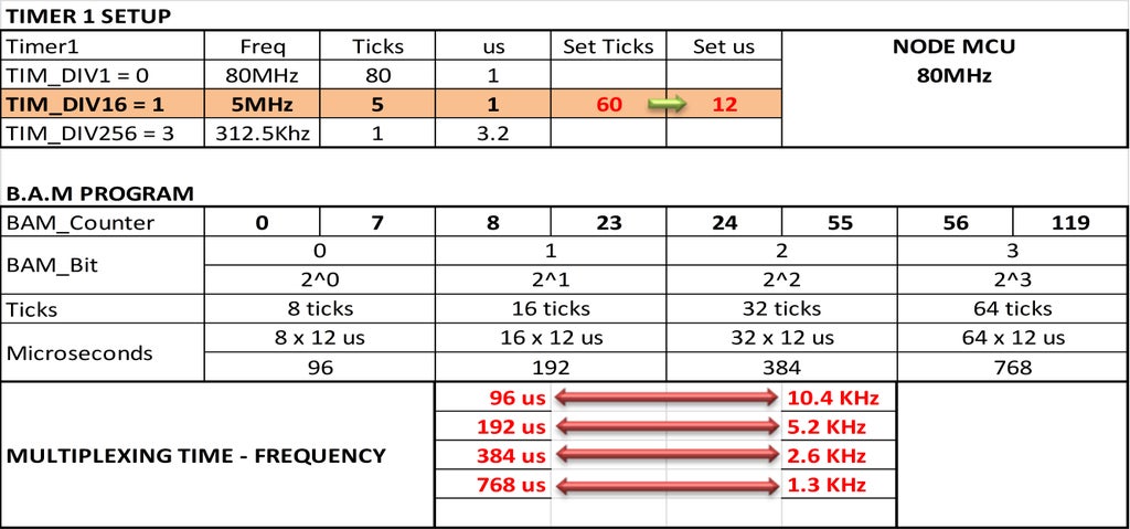
I marked my timer1_ISR() with ICACHE_RAM_ATTR attribute to avoid an illegal instruction error when interrupt happens.
void ICACHE_RAM_ATTR timer1_ISR(void);
For row scanning, firstly, I want to speed up my code by using direct control digital pins like this.
//Setting the pin HIGH

GPOS = (1 << RowA_Pin);

//Setting the pin LOW

GPOC = (1 << RowA_Pin);
But it was really too fast, even some rows of matrix panel could not be displayed so I had to turn back traditional pin control with "digitalWrite". It worked great because NODEMCU has 80MHz clock speed :-)
void rowScan(byte row) {

  if (row & 0x01) digitalWrite(RowA_Pin,HIGH);
    else          digitalWrite(RowA_Pin,LOW);
  if (row & 0x02) digitalWrite(RowB_Pin,HIGH);
    else          digitalWrite(RowB_Pin,LOW);
  if (row & 0x04) digitalWrite(RowC_Pin,HIGH);
    else          digitalWrite(RowC_Pin,LOW);
  if (row & 0x08) digitalWrite(RowD_Pin,HIGH);
    else          digitalWrite(RowD_Pin,LOW);
}
Main attach interrupt service routine:
void ICACHE_RAM_ATTR timer1_ISR(void)
{
  digitalWrite(blank_pin, HIGH);  // Set BLANK PIN high - 74HC595 & 74HC238
  if(BAM_Counter==6)	// Bit weight 2^0, lasting time = 6 ticks x interrupt interval time
  BAM_Bit++;
  else
  if(BAM_Counter==18)   // Bit weight 2^1, lasting time = 18 ticks x interrupt interval time
  BAM_Bit++;
  else
  if(BAM_Counter==42)   // Bit weight 2^3, lasting time = 42 ticks x interrupt interval time
  BAM_Bit++;
  BAM_Counter++;
  switch (BAM_Bit)
    {
    case 0:
      //Red
        SPI.transfer(red[0][level + 0]);
        SPI.transfer(red[0][level + 1]);
        SPI.transfer(red[0][level + 2]);
        SPI.transfer(red[0][level + 3]);
        SPI.transfer(red[0][level + 64]);
        SPI.transfer(red[0][level + 65]);
        SPI.transfer(red[0][level + 66]);
        SPI.transfer(red[0][level + 67]);
      //Green
        SPI.transfer(green[0][level + 0]);
        SPI.transfer(green[0][level + 1]);
        SPI.transfer(green[0][level + 2]);
        SPI.transfer(green[0][level + 3]);
        SPI.transfer(green[0][level + 64]);
        SPI.transfer(green[0][level + 65]);
        SPI.transfer(green[0][level + 66]);
        SPI.transfer(green[0][level + 67]);
      break;
    case 1:
      //Red
        SPI.transfer(red[1][level + 0]);
        SPI.transfer(red[1][level + 1]);
        SPI.transfer(red[1][level + 2]);
        SPI.transfer(red[1][level + 3]);
        SPI.transfer(red[1][level + 64]);
        SPI.transfer(red[1][level + 65]);
        SPI.transfer(red[1][level + 66]);
        SPI.transfer(red[1][level + 67]);
      //Green
        SPI.transfer(green[1][level + 0]);
        SPI.transfer(green[1][level + 1]);
        SPI.transfer(green[1][level + 2]);
        SPI.transfer(green[1][level + 3]);
        SPI.transfer(green[1][level + 64]);
        SPI.transfer(green[1][level + 65]);
        SPI.transfer(green[1][level + 66]);
        SPI.transfer(green[1][level + 67]);
      break;
    case 2:
      //Red
        SPI.transfer(red[2][level + 0]);
        SPI.transfer(red[2][level + 1]);
        SPI.transfer(red[2][level + 2]);
        SPI.transfer(red[2][level + 3]);
        SPI.transfer(red[2][level + 64]);
        SPI.transfer(red[2][level + 65]);
        SPI.transfer(red[2][level + 66]);
        SPI.transfer(red[2][level + 67]);
       //Green
        SPI.transfer(green[2][level + 0]);
        SPI.transfer(green[2][level + 1]);
        SPI.transfer(green[2][level + 2]);
        SPI.transfer(green[2][level + 3]);
        SPI.transfer(green[2][level + 64]);
        SPI.transfer(green[2][level + 65]);
        SPI.transfer(green[2][level + 66]);
        SPI.transfer(green[2][level + 67]);
      break;
    case 3:
      //Red
        SPI.transfer(red[3][level + 0]);
        SPI.transfer(red[3][level + 1]);
        SPI.transfer(red[3][level + 2]);
        SPI.transfer(red[3][level + 3]);
        SPI.transfer(red[3][level + 64]);
        SPI.transfer(red[3][level + 65]);
        SPI.transfer(red[3][level + 66]);
        SPI.transfer(red[3][level + 67]);
      //Green
        SPI.transfer(green[3][level + 0]);
        SPI.transfer(green[3][level + 1]);
        SPI.transfer(green[3][level + 2]);
        SPI.transfer(green[3][level + 3]);
        SPI.transfer(green[3][level + 64]);
        SPI.transfer(green[3][level + 65]);
        SPI.transfer(green[3][level + 66]);
        SPI.transfer(green[3][level + 67]);
    if(BAM_Counter==90)    //Bit weight 2^3, lasting time = 90 ticks x interrupt interval time
    {
    BAM_Counter=0;
    BAM_Bit=0;
    }
    break;
  }
  rowScan(row);
  digitalWrite(latch_pin, HIGH);    // Set LATCH PIN low - 74HC595
  digitalWrite(latch_pin, LOW);     // Set LATCH PIN low - 74HC595
  digitalWrite(blank_pin, LOW);     // Set BLANK PIN low - 74HC595 & 74HC238
  row++;
  level = row<<2;
  if(row==16)
  row=0;
  if(level==64)
  level=0;
  timer1_write(60);     //Interrupt interval time 60 x 0.2us = 12us
}
To adjust and calibrate the led matrix, we can change the elapsed time on bit weight of BAM_Bit (4 bit) following below rule:

You can play with above numbers of BAM_Counter and timer_write(xx) to find out your best parameters. Finally for me, I setup:
- timer1_write(60).
- BAM_Bit Tick numbers: 6, 18, 42, 90.
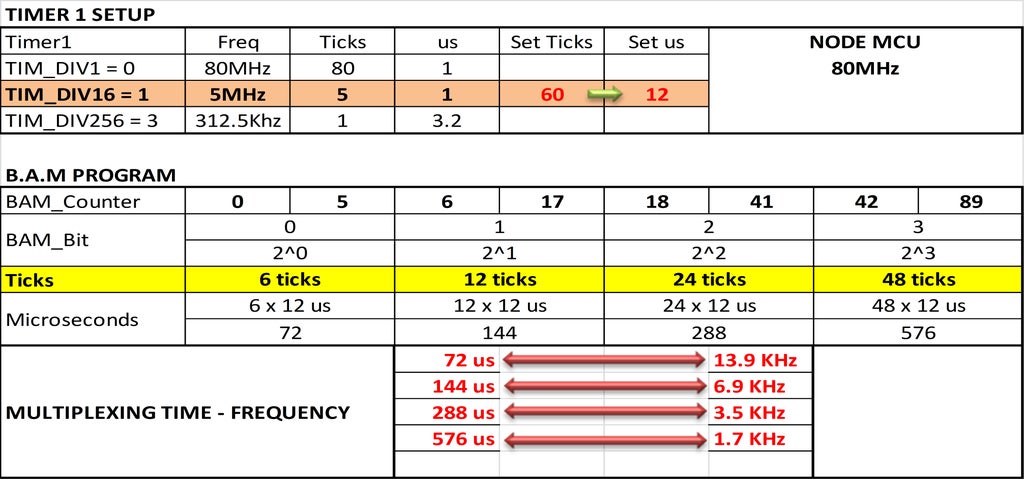
You can download this table template in Excel format here: NODEMCU_TIMER1_BAM. It shows the relationship between interrupt interval time and how many Ticks for the lowest bit weight - BAM Bit - are selected.
The project code for NODEMCU is available at my GitHub:
Step 6: LED BOARD TESTING
We can use some online tools for converting image file to C/C++ code by google key word "convert image to hex". Or we can convert animation GIF file to many separated images then convert these images to HEX code.
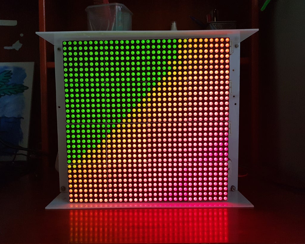
- Rainbow Testing: picture below shows the different colors of LEDs that are generated from the B.A.M process.
Here below are some projects that made me excited. With some slight modified, I can reuse them on my led board and Arduino Mega 2560. Thank to HariFun and TobiasB48 for their Morphing Digital Clock and Tetris Clock .
- Morphing Digital Clock from HariFun
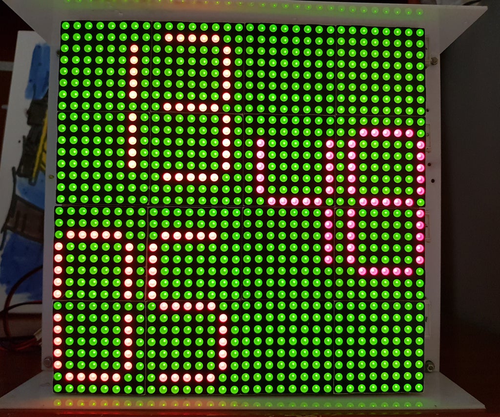
I declared digit in "typedef struct" and updated clock with background color as below:
typedef struct
{
byte _value;
uint16_t xOffset;
uint16_t yOffset;
Color _color;
Color _bgcolor;
} Digit;
My code for Morphing Digital Clock is available at GitHub link:
https://github.com/tuenhidiy/DIGITAL_CLOCK_MATRIX_...
- Tetris Time Clock from TobiasB48
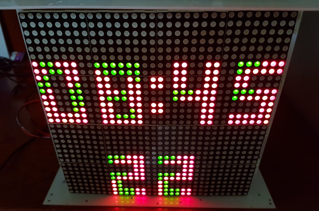
Original version from TobiasB48 displayed the time on RGB matrix 16x32. For my Tetris Clock, with some modification, it can show hour, minute and second on bicolor matrix 32x32. Tetris Clock effect looks great and I can look at it all day :-)
My code for Tetris Clock is available at GitHub:
https://github.com/tuenhidiy/TETRIS_CLOCK_MATRIX_3...
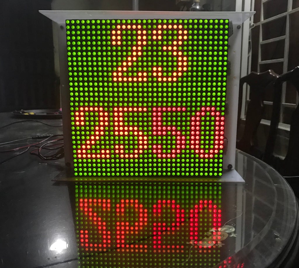
- Handwritten Clock Version 1:
- Handwritten Clock Version 2:
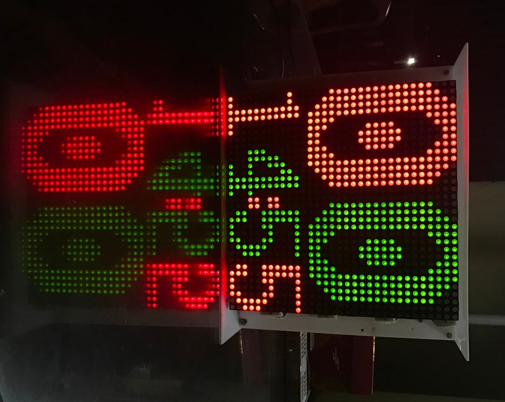
For 2 versions of handwritten clocks, I created 3 handwritten font sizes:
*** Small font size 7x11.
*** Inverted small font size 8x16.
*** Big font size 14x20.
For Handwritten Clock version 1, I used small and inverted small number fonts for clock effects. With Handwritten Clock version 2, I combined small and big number fonts to show time on matrix 32x32. They are both look very amazing.
My code for Handwritten Clock is available at GitHub:
Step 7: FINISH
Here are some pictures for my projects.
Thank you for reading to the last page.

Participated in the
Colors of the Rainbow Contest


