Introduction: How to Make the Robot "BitTempo: Your Time, Your Style"


At the Manuel Rosado Iguarán school in Maicao, Colombia, an exciting and visionary project is underway that combines micro:bit technology with the rich tradition of the Wayuu indigenous community. Talented young people are collaborating to design and program a unique digital watch, powered by the versatile micro:bit. This smart watch not only marks the passage of time, but also fulfills a vital function: ringing school hours. This innovative application of technology not only promotes punctuality and organization in the school environment, but also encourages cultural pride and active participation of students in creating solutions that positively impact their community. It is a powerful testament to how education, technology and the innovative spirit can come together to inspire change and open new opportunities for learning and growth.
As a 28-year-old teacher with high school youth, I feel proud to share with you this experience made in Colombia in the municipality of Maicao.
Supplies

micro bit.
Shield for micro bit.
RTC ds3231.
easy connection cables (Jumpers).
Breadboard 5v source.
lcd1602.
relay.
Step 1: Connect RTC and LCD SCREEN


Identify pins on the DS3231 RTC module:
They usually have pins such as VCC (power), GND (ground), SDA (serial data line), and SCL (serial clock line).
Connect the power:
Connect the VCC pin of the RTC module to the 5V pin of the supply
Connect the GND pin of the RTC module to the GND pin of the supply.
Connect the data and clock lines:
Connect the SDA pin of the RTC module to the SDA Pin(20 ) of the micro:bit.
Connect the SCL pin of the RTC module to the SCL Pin Pin(19) of the micro:bit.
Identify pins on the LCD1602 module:
The LCD1602 module usually has a set of pins for power, contrast, data input/output, and I2C connection. Identify these pins before you begin.
Connect the power:
Connect the VCC pin of the LCD1602 module to the 5V pin of the supply.
Connect the GND pin of the LCD1602 module to the GND pin of the power supply.
Connect the data and clock lines (I2C):
Connect the SDA (data) pin of the LCD1602 module to the SDA Pin(20) of the micro:bit.
Connect the SCL (clock) pin of the LCD1602 module to the SCL Pin(19) of the micro:bit.
PLEASE DON'T FORGET TO CONNECT THE GND OF THE PROTOBOARD SOURCE TO THE GND OF THE EXTENSION SO THAT THE VOLTAGES CAN BE BALANCED AND THE PROGRAMMING CAN BE EXECUTED WELL
Step 2: Relay and Button Connection

Connecting a relay to a Micro:bit is a simple process:
- positive pin at 5v from the supply.
- Negative pin to gnd of the source.
- and pin with the letter S or signal to Pin (8) (or your preference) of the micro bit.
The button, on the other hand, works at 3v and we will use the Pin (10) (or your preference) to activate or deactivate programmed times.
Step 3: Programming Step 1 (Download RTC Extension )


We open MAKE CODE on the official website and go to the extensions block.
We write RTC in the search engine and install the library called "Download RTC Extension
"We click on it and it will be installed
Step 4: Download Lcd Library 1602


To install the LCD screen extension, enter the extensions block again and install the Maker bit LCD1602 extension.
Step 5: Lcd Test 1602


Using the installed "Maker Bit" extension for the 1602 LCD, drag the connect lcd i2c block to the block at startup, this will serve so that every time you start the micro bit the connection bus is created.
then in the seed block choose "LCD1602SHOW" to show letters, variables or text at the coordinate you want on the LCD.
example I used "Hello." in position 7-16
and then "INSTRUCTABLES" position 19 - 16.
So hello instructables!!
Step 6: SET TIME AND DATE ON THE RTC DS3231


Set the exact time and date with the building block.
Set according to the date you have on your cell phone and in the "day" part it is ordered like this:
1 = Monday
2 = Tuesday
3 = Wednesday
4 = Thursday
5 = Friday
6 = Saturdays
7 = Sunday
We will make this item a separate function to be able to decorate our watch.
When you finish setting the date and time, download the schedule.

then delete the block and download it again to the micro bit, in this way the time will be permanently recorded.
Step 7: Create Date and Time Block on the Screen.


First we create the function that will tell us what day of the week we are on, we store the item "day" from the rtc library in it and we establish the comparative logic:
If day is equal to 1 write "Monday"
If day is equal to 2 write "Tuesday" etc etc
Then structure the construction on the screen like the programming that I show you here in the image, you simply have to be attentive and place your time and date settings as you like.
REMEMBER TO CALL THE DIA FOUNDATION FIRST FOR IT TO BE EXECUTED.
Step 8: Watch Results When Downloading

Make the connections and download the programming to the card, test and create the locations or characters to your liking.

Download the 3D model and build your precision digital clock.

I hope to teach you how to program ringing times another time.
Step 9: Final Result and Assembly.

Assemble your watch and place it in a place that makes you proud. Thank you for following, I hope I have helped you a lot
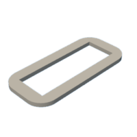
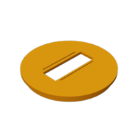
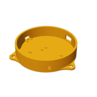
Step 10: 3D Models to Print.

Here I leave you the design that I have made in fusion 360 so that you can arrange the pieces inside and seal.

There is also the hole for the button so you can solder it and keep it fixed.

Participated in the
Robotics Contest


![Tim's Mechanical Spider Leg [LU9685-20CU]](https://content.instructables.com/FFB/5R4I/LVKZ6G6R/FFB5R4ILVKZ6G6R.png?auto=webp&crop=1.2%3A1&frame=1&width=306)


