Introduction: How to Properly Drive 4 Digit 7 Segment Display Using Arduino


It is number of instructables describing how to connect 4 digit 7 segment display to Arduino 1,2,3,4,5
These instructables good enough if you want to do fast breadboard project for fun. But if you want to do serious project it is better way to do this.
BTW. I am assuming you have general understanding how 7 segment display works. If not, you can read explanations provided in instructables i referenced above.
Step 1: Hardware
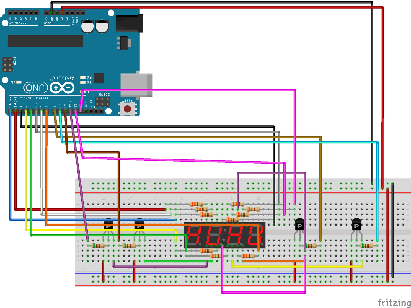
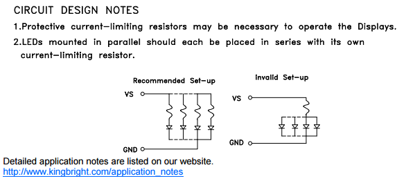

1. In most instructables for each digit used single resistor connected to common anode/cathode. This works for fast breadboard project, but not recommended for serious projects. For such connection segments current and therefore digit brightness depends on how many segments working. So different numbers will have different brightness, that is ugly. proper way to do this is to use resistor for each segment. In this case you will need 8 resistors instead of 4, but the brightness will be constant.
2. In most instructables common anode/cathode connected directly to the Arduino board I/O pin. Generally it is a wrong way. For most displays maximum current per segment is 10-20mA. So total current can be 80-160mA. Arduino can source/sink up to 40mA per I/O pin. So the better way to connect common anode/cathode to supply using transistor to amplify current. In this way maximum current per segment can be used, that will allow maximum brightness of display.
Step 2: Parts Used

Of cause this is only example of implementation. Same concepts will work with any 7 segment display. Separate digits can be uses as well.
Common anode 4-digit 7-segment display
PNP transistor 2N3906 x4
Resistors 610 Ohm x14 Because it is only proof of concept all resistors are same. You should, of cause, choose resistors according to maximum current of 7-segment display and current gain of used transistor.
I used separate 5V supply for components on breadboard. Generally it should be ok to connect all components to Arduino board. In this case it will be good if you will connect 100 microfarad capacitor between positive and negative supply lines of breadboard.
Step 3: Software
In most instructables, code that controls display called from loop() function. This approach generally works, but frame-rate and brightness will change when you add or remove code from loop() function. Also in most cases display will flicker on video. This behavior not desired for serious project.
The better way is to control display from function called by interrupt. Attached class implements display control using Timer1 for interrupt. 16 levels of brightness control implemented as well.
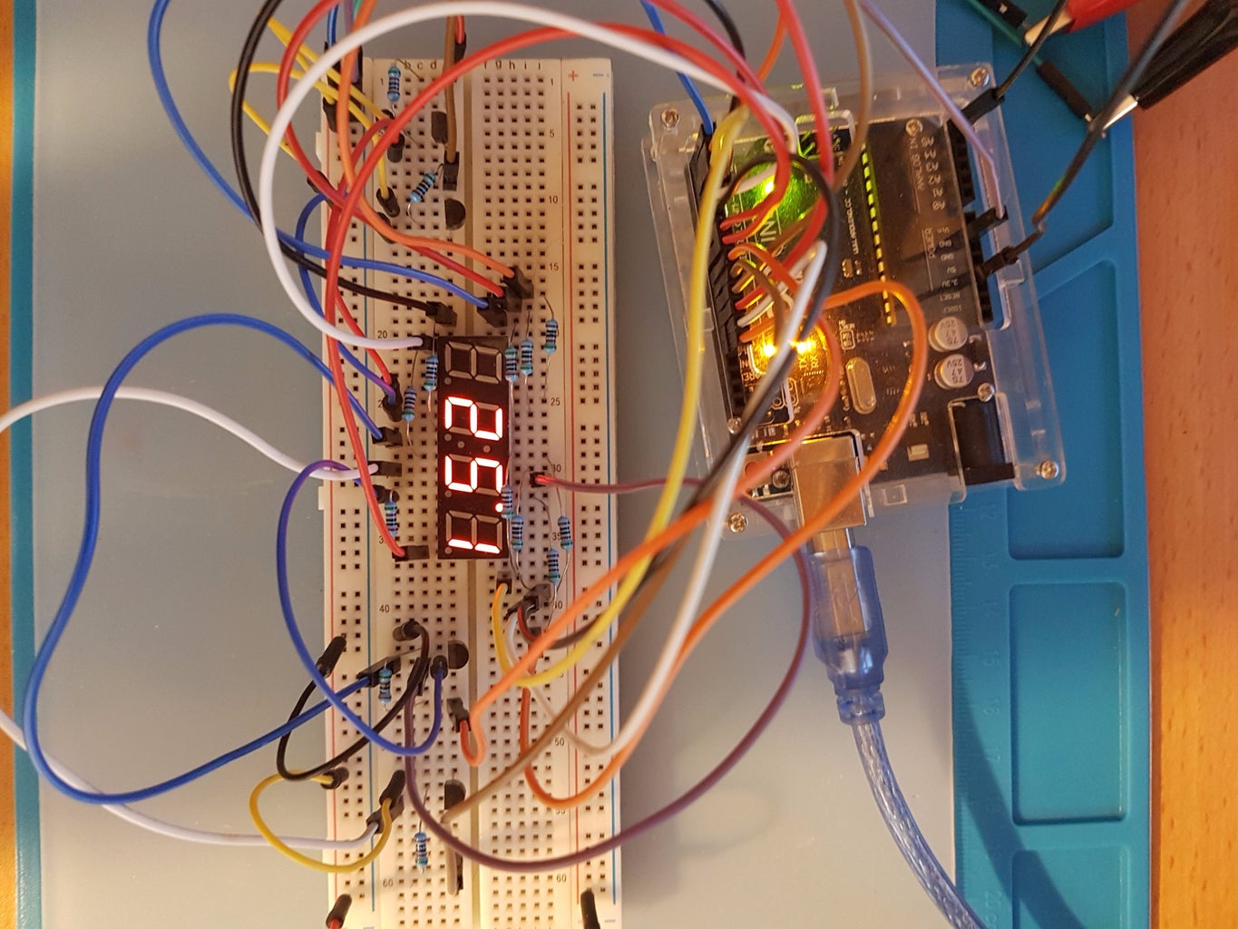
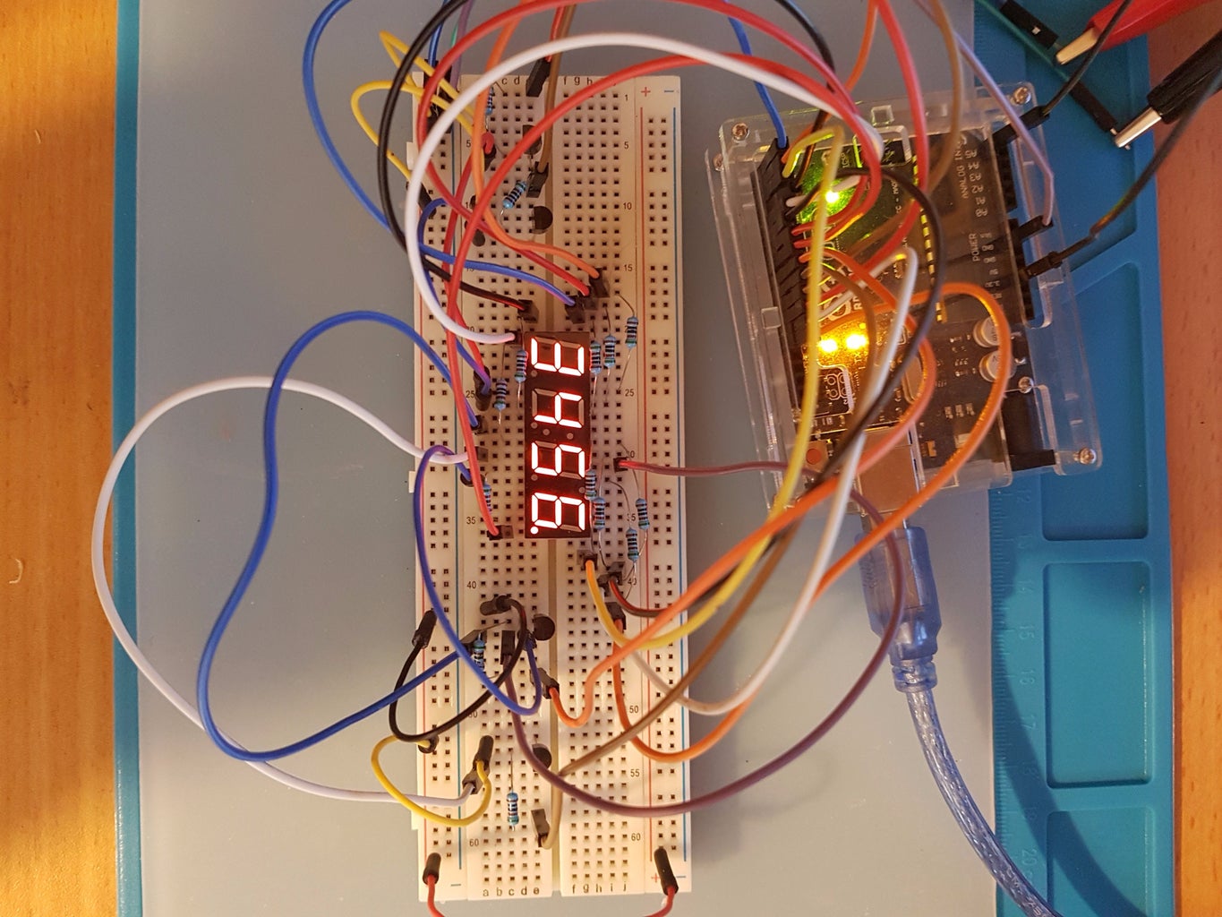
Included sketch my_4digit_7segment_one.ino demonstrates different uses of class for controlling display including clock and temperature display.
The code has lot of comments, so it is easy to adapt it to different type of 7 segment display. It also can be adapred control more then one display or separate digits.
Attachments

Step 4: Code Perfomance

Display refreshing function called from interrupt once every 63 microsecond. Time inside function measured with oscilloscope approximately 3.5 microseconds. So the code uses less then 6% of microprocessor time.
Frame rate is approximately 248 FPS.
Step 5: No Flickering Video

Participated in the
Microcontroller Contest 2017

Participated in the
Lights Contest 2017


