Introduction: How to Program Attiny Using Arduino Uno
I just wanted to make a small arduino for my few projects because buying a arduino for every project will be too expensive for a 15 yrs old guy !!!!!
Step 1: Things You Need
arduino IDE
attiny files on ur arduino IDE
You can download the files given below and move the files in hardware
1- arduino uno
1- attiny 45 or 85
1- breadboard
few jumper wires
1- 10 uf capacitor
Optional (if you u want it permanent )
1- perfboard
1- 1 led any colour that u like
1- 220 ohms resistor
and some pin headers
Step 2: Lets Get Starded
Open the arduino IDE
and open the arduino isp sketch from the examples and upload it on your uno Note(don't connect anything to arduino while uploading the isp sketch).
and open the arduino isp sketch from the examples and upload it on your uno Note(don't connect anything to arduino while uploading the isp sketch).
Step 3: Step 3:- Connecting It With Attiny
Unplug ur uno from the computer and connect it with attiny as shown in the picture below after wiring it then connect the 10uf capacitor the + wire to the reset pin and the - wire to gnd pin after wiring it connect it with usb
Here are the pinout
attiny pin 1- arduino pin 10
attiny pin 5- arduino pin 11
attiny pin 6- arduino pin 12
attiny pin 7- arduino pin 13
attiny pin 4- gnd
attiny pin 8- 5v
TA ADA!!!!!!!! now u can program attiny
UPDATE: Here is the schematic of the attiny programmer with the led and capacitor , there is also a pcb view of the shield
Step 4: Making the Circuit Permanent
I made the circuit because i need to program more attiny's so it would be consume time for making the circuit again and again
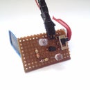
here are some photos of the shield I hav also added a led in the shield and also check the video
here are some photos of the shield I hav also added a led in the shield and also check the video


