

Introduction: Interfacing 16X2 LCD With STM32 & Cube IDE


Hello!
In this tutorial, you’ll learn how to interface STM32 with LCD 16×2 display and integrate the STM32 LCD library into your project.
Supplies
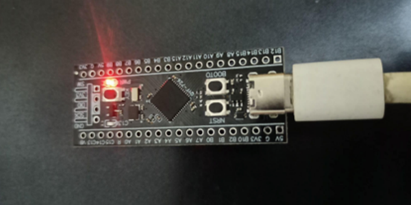
- STM32 Black pill board
- STM32 Cube IDE Software
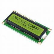
- 16*2 LCD Display
- Jumper wires (M-M, F-M)
- USB –Type C cable
- Potentiometer- 10K
- Breadboard
Step 1: MAKE CONNECTIONS

- The first step is to make connections between the components.
- Make pin connection between LCD display and STM32 black pill board as shown in the images.
- Also use breadboard to connect potentiometer and resistor to LCD display and STM32 board.
- The project will work without making use of potentiometer and resistor but it is better to use potentiometer for display quality and resistor for durability.
Step 2: STM32 Cube IDE Pin Settings

- Open Cube IDE and go to Pinout and Configuration
- Now in Pinout view select the pins that you used in the hardware connections
- Here from the above step set PA1, PA3, PB0, PB1, PB10 and PB11 to GPIO_Output
- Now, to setup timer to create delay in microseconds, click on clock configuration >>HSE>>PLL CLK
- Now, select resolve clock issues from the top in the center
- Save the settings
Step 3: Program : Code for Libraries(Inside Core/Inc Folder)
- Add code in Inc folder that is inside Core
- The code is given below:
/*
* lcd.h
*
* Created on: 10/06/2018
* Author: Olivier Van den Eede
*/
#ifndef LCD_H_
#define LCD_H_
#include "stm32f1xx_hal.h"
#include "string.h"
#include "stdio.h"
#include "main.h"
// #define LCD20xN // For 20xN LCDs
#define LCD16xN // For 16xN LCDs
// For row start addresses
extern const uint8_t ROW_16[];
extern const uint8_t ROW_20[];
/************************************* Command register **************************************/
#define CLEAR_DISPLAY 0x01
#define RETURN_HOME 0x02
#define ENTRY_MODE_SET 0x04
#define OPT_S 0x01 // Shift entire display to right
#define OPT_INC 0x02 // Cursor increment
#define DISPLAY_ON_OFF_CONTROL 0x08
#define OPT_D 0x04 // Turn on display
#define OPT_C 0x02 // Turn on cursor
#define OPT_B 0x01 // Turn on cursor blink
#define CURSOR_DISPLAY_SHIFT 0x10 // Move and shift cursor
#define OPT_SC 0x08
#define OPT_RL 0x04
#define FUNCTION_SET 0x20
#define OPT_DL 0x10 // Set interface data length
#define OPT_N 0x08 // Set number of display lines
#define OPT_F 0x04 // Set alternate font
#define SETCGRAM_ADDR 0x040
#define SET_DDRAM_ADDR 0x80 // Set DDRAM address
/************************************** Helper macros **************************************/
#define DELAY(X) HAL_Delay(X)
/************************************** LCD defines **************************************/
#define LCD_NIB 4
#define LCD_BYTE 8
#define LCD_DATA_REG 1
#define LCD_COMMAND_REG 0
/************************************** LCD typedefs **************************************/
#define Lcd_PortType GPIO_TypeDef*
#define Lcd_PinType uint16_t
typedef enum {
LCD_4_BIT_MODE,
LCD_8_BIT_MODE
} Lcd_ModeTypeDef;
typedef struct {
Lcd_PortType * data_port;
Lcd_PinType * data_pin;
Lcd_PortType rs_port;
Lcd_PinType rs_pin;
Lcd_PortType en_port;
Lcd_PinType en_pin;
Lcd_ModeTypeDef mode;}
Lcd_HandleTypeDef;
/************************************** Public functions **************************************/
void Lcd_init(Lcd_HandleTypeDef * lcd);
void Lcd_int(Lcd_HandleTypeDef * lcd, int number);
void Lcd_string(Lcd_HandleTypeDef * lcd, char * string);
void Lcd_cursor(Lcd_HandleTypeDef * lcd, uint8_t row, uint8_t col);
Lcd_HandleTypeDef Lcd_create(
Lcd_PortType port[], Lcd_PinType pin[],
Lcd_PortType rs_port, Lcd_PinType rs_pin,
Lcd_PortType en_port, Lcd_PinType en_pin, Lcd_ModeTypeDef mode);
void Lcd_define_char(Lcd_HandleTypeDef * lcd, uint8_t code, uint8_t bitmap[]);
void Lcd_clear(Lcd_HandleTypeDef * lcd);
#endif /* LCD_H_ */
Step 4: Program : Code for Libraries(Inside Core/Src Folder)
/*
* lcd.c
*
* Created on: 10/06/2018
* Author: Olivier Van den Eede
*/
#include "lcd.h"
const uint8_t ROW_16[] = {0x00, 0x40, 0x10, 0x50};
const uint8_t ROW_20[] = {0x00, 0x40, 0x14, 0x54};
/************************************** Static declarations **************************************/
static void lcd_write_data(Lcd_HandleTypeDef * lcd, uint8_t data);
static void lcd_write_command(Lcd_HandleTypeDef * lcd, uint8_t command);
static void lcd_write(Lcd_HandleTypeDef * lcd, uint8_t data, uint8_t len);
/************************************** Function definitions **************************************/
/**
* Create new Lcd_HandleTypeDef and initialize the Lcd
*/
Lcd_HandleTypeDef Lcd_create(
Lcd_PortType port[], Lcd_PinType pin[],
Lcd_PortType rs_port, Lcd_PinType rs_pin,
Lcd_PortType en_port, Lcd_PinType en_pin, Lcd_ModeTypeDef mode)
{
Lcd_HandleTypeDef lcd;
lcd.mode = mode;
lcd.en_pin = en_pin;
lcd.en_port = en_port;
lcd.rs_pin = rs_pin;
lcd.rs_port = rs_port;
lcd.data_pin = pin;
lcd.data_port = port;
Lcd_init(&lcd);
return lcd;
}
/**
* Initialize 16x2-lcd without cursor
*/
void Lcd_init(Lcd_HandleTypeDef * lcd)
{if(lcd->mode == LCD_4_BIT_MODE)
{lcd_write_command(lcd, 0x33);
lcd_write_command(lcd, 0x32);
lcd_write_command(lcd, FUNCTION_SET | OPT_N); // 4-bit mode
}
else
lcd_write_command(lcd, FUNCTION_SET | OPT_DL | OPT_N);
lcd_write_command(lcd, CLEAR_DISPLAY); // Clear screen
lcd_write_command(lcd, DISPLAY_ON_OFF_CONTROL | OPT_D); // Lcd-on, cursor-off, no-blink
lcd_write_command(lcd, ENTRY_MODE_SET | OPT_INC); // Increment cursor
}
/**
* Write a number on the current position
*/
void Lcd_int(Lcd_HandleTypeDef * lcd, int number)
{
char buffer[11];
sprintf(buffer, "%d", number);
Lcd_string(lcd, buffer);
}
/**
* Write a string on the current position
*/
void Lcd_string(Lcd_HandleTypeDef * lcd, char * string)
{
for(uint8_t i = 0; i < strlen(string); i++)
{lcd_write_data(lcd, string[i]);
}
}
/**
* Set the cursor position
*/
void Lcd_cursor(Lcd_HandleTypeDef * lcd, uint8_t row, uint8_t col)
{
#ifdef LCD20xN
lcd_write_command(lcd, SET_DDRAM_ADDR + ROW_20[row] + col);
#endif
#ifdef LCD16xN
lcd_write_command(lcd, SET_DDRAM_ADDR + ROW_16[row] + col);
#endif
}
/**
* Clear the screen
*/
void Lcd_clear(Lcd_HandleTypeDef * lcd) {
lcd_write_command(lcd, CLEAR_DISPLAY);
}
void Lcd_define_char(Lcd_HandleTypeDef * lcd, uint8_t code, uint8_t bitmap[]){
lcd_write_command(lcd, SETCGRAM_ADDR + (code << 3));
for(uint8_t i=0;i<8;++i){
lcd_write_data(lcd, bitmap[i]);
}
}
/************************************** Static function definition **************************************/
/**
* Write a byte to the command register
*/
void lcd_write_command(Lcd_HandleTypeDef * lcd, uint8_t command)
{
HAL_GPIO_WritePin(lcd->rs_port, lcd->rs_pin, LCD_COMMAND_REG); // Write to command register
if(lcd->mode == LCD_4_BIT_MODE)
{lcd_write(lcd, (command >> 4), LCD_NIB);
lcd_write(lcd, command & 0x0F, LCD_NIB);}
else
{lcd_write(lcd, command, LCD_BYTE);}
}
/**
* Write a byte to the data register
*/
void lcd_write_data(Lcd_HandleTypeDef * lcd, uint8_t data)
{
HAL_GPIO_WritePin(lcd->rs_port, lcd->rs_pin, LCD_DATA_REG); // Write to data register
if(lcd->mode == LCD_4_BIT_MODE)
{lcd_write(lcd, data >> 4, LCD_NIB);
lcd_write(lcd, data & 0x0F, LCD_NIB);}
else
{lcd_write(lcd, data, LCD_BYTE);}
}
/**
* Set len bits on the bus and toggle the enable line
*/
void lcd_write(Lcd_HandleTypeDef * lcd, uint8_t data, uint8_t len
{
for(uint8_t i = 0; i < len; i++)
{HAL_GPIO_WritePin(lcd->data_port[i], lcd->data_pin[i], (data >> i) & 0x01);}
HAL_GPIO_WritePin(lcd->en_port, lcd->en_pin, 1);
DELAY(1);
HAL_GPIO_WritePin(lcd->en_port, lcd->en_pin, 0); // Data receive on falling edge
}
- Save and close the files
Step 5: Program for Main.c
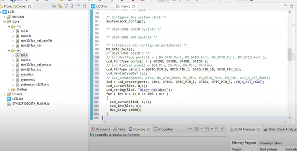
- Add #include "lcd.h" under /* USER CODE BEGIN Includes */
- Additional code on top of STM32CubeIDE generated code is given below:
// Lcd_PortType ports[] = { D4_GPIO_Port, D5_GPIO_Port, D6_GPIO_Port, D7_GPIO_Port };
Lcd_PortType ports[] = { GPIOB, GPIOB, GPIOB, GPIOB };
// Lcd_PinType pins[] = {D4_Pin, D5_Pin, D6_Pin, D7_Pin};
Lcd_PinType pins[] = {GPIO_PIN_0, GPIO_PIN_1, GPIO_PIN_10, GPIO_PIN_11};
Lcd_HandleTypeDef lcd;
// Lcd_create(ports, pins, RS_GPIO_Port, RS_Pin, EN_GPIO_Port, EN_Pin, LCD_4_BIT_MODE);
lcd = Lcd_create(ports, pins, GPIOA, GPIO_PIN_1, GPIOA, GPIO_PIN_3, LCD_4_BIT_MODE);
Lcd_cursor(&lcd, 0,1);
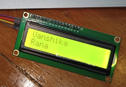
Lcd_string(&lcd, "Vanshika Rana");
for ( int x = 1; x <= 200 ; x++ )
{
Lcd_cursor(&lcd, 1,7);
Lcd_int(&lcd, x);
HAL_Delay (1000);}
Step 6: Cube Programmer
- Now, copy path of project file generated
- Open STM32 cube programmer>>main.c (beside Device memory)>> Open file
- Enter file path and connect the STM32 black pill via USB cable
- Click on Download and fill the blank space with file path. Check the boxes and click on Start Automatic Mode
- The LCD displays your name


![Tim's Mechanical Spider Leg [LU9685-20CU]](https://content.instructables.com/FFB/5R4I/LVKZ6G6R/FFB5R4ILVKZ6G6R.png?auto=webp&crop=1.2%3A1&frame=1&width=306)


