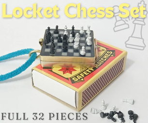
Introduction: Light Stimulated Hourglass

Light is my all time love while creating crafts.
This is an unusual hourglass which replace sand with cool color lights. The hourglass could count down from a minute to 10 minutes. The lighten hight will decline as time passes. Furthermore, the light's color will change and mix into several blues and purple.
You could put this hourglass on the desk or the shelf as a decoration of your room. Meanwhile, you could adjust the time, used as a timer.
This light stimulated hourglass has mimic the outlook and felling of an hourglass. You could never estimate the leaking time!
Supplies
Wooden Board (8mm thick)
Light Guide Plates
RGD LED Light (5mm) * 2
Blue LED Light (5mm) * 2
Variable Resistor * 1
Ribbon Cables * 9
Hinge
Screws * 6
Screwdriver
Solder
Soldering Iron
Wires
Arduino Leonardo
Saw
Wire Saw
Sandpaper
File (Sharp & Flat)
Planer
Paper Knife
Drill (1mm ~ 5mm)
Electric Mini Grinder
White Glue
Hot Glue
Hot Glue Gun
Right Angle Fixing Clip
Unity Holder
Later Cut Machine
Pliers
Flamethrower
Step 1: Draw Out the Pattern You Like

Draw out the pattern you like to see while the lights are added with Adobe Illustrator. A general rule: the more tight the pattern is, the more light it will gather at that spot. If you like the light to past through the entire light guide board, circle might be one the safe choices. My pattern design is included below, you may download the file if you are afraid to draw one by yourself.
Attachments

Step 2: Laser Cutter
Use the laser cutter to cut down the 6 pieces of light guide board and tear off the protection sheet on it. You may use sandpaper to smoothen the sides and blow off or wash off small scraps. While using the laser cutter, the laser speed and power should be tried before cutting the final. It usually takes 15 minutes to cut six boards off.
Step 3: Prepare for the Base


A 8cm * 10cm wooden box will be as the base of the hourglass. First, draw down the six pieces: top & bottom (10cm * 10cm), and four side (9cm * 6cm). Then use a saw to slice the wood into the part you drawn. Later on, use sandpaper to flatten the sides, this allows the white glue to stick more properly.
Step 4: Stick the Four Sides


Before sticking the four sides, I will prefer to first place them into the shape I excepted. If the sides fit, then squeeze enough amount of white glue on one side and wait for 30 seconds. When we let the white glue drys for a moment, the glue usually become more stackable. I use a right angle fixing clip to maintain the 90 degree of two sides. Do this process twice and you will end with two L shape. Afterward, then glue the two L shape together and it forms a square. Next, the unity holder should be tided around the sides. By giving pressure to the sides, less gaps and air bubbles will form when drying. Remember to tight the string or else it will not perform the way you thought!
Step 5: Trench for the Light Guide Board


Three light guide board were been used in my project. Before carving the trench out, I prefer to draw out the position where I like the board to be placed. For speeding the process, I will first dig a hole with a drill. Second, use the electric mini grinder to cut out the length. This allow me to follow the line better while opening the trench with files. Third, use a sharp file to open the trench until the wide file could fit. After the wide file fits, use a saw to first cut through the path and then the wide file follows. When you feel that the size is near the wide of the light guide board, then tries to place the board inside. Be careful the wide and the length of the trench. If the board did not fit the trench, then you should use A LOT hot glue. However, it weak and looks bad if it is oversize.
Step 6: Clean the Top Board
After digging the trenches, the top board might look dirty. At this time, you may use the sandpaper to clear the surface of the wooden plate and use a paper knife to carve out the extra sawdust. If you want your box to be more polished, then toner the wood might be a choice. But this time, I decide to not include this process.
Step 7: Twist the Light Guide Board

By twisting the light guide board, the light could cover a wider region. Also, it creates a wave look and seems to be more beauty. Two pliers and a flamethrower are used. Firstly, temporarily fix the light guide board onto the wooden top plate. Secondly, heat the part you want to turn with the flamethrower. 15 to 30 seconds is long enough. If you overheated the light guide board, it will become too soft for you to control the board into the shape you wish for. While the board starts to become transparent, you may twist the board with the plier at the spot you like. After you are sure for the angle, turn off the flamethrower completely and cold the board with water or strong wind. Before the board resume its hardness, hold in the same position and wait.
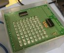
Step 8: LED Lights ON


As the same as before, always first mark the position before doing any action. First draw out where the LED should be placed then use sharpe file to dig out the hole. The hole should be a the middle of the board. For the round circle design board, one LED is required. For the bubble and air popping design board, two RGB LED lights are required. Next, tug the board into the trenches and check the height. Hold the board and glue the board with hot glue and wait for it drys. When the position is set, use the hot glue to stick the LED lights into the hole. If you can keep the light horizontally with the board, the result will look better.
Step 9: Place the Bottom Plate On


For the convince soldering all the pins and fix them if something bad happens. I decided to add a hinge to it. Before adding the hinge on, we must make sure all four sides are flat to others. If not, then you may use a planer to remove all the unnecessary height. Both the top and bottom should be flatted. Four screws are needed in this process. Firstly, mark where the hinge should be, then use the drill to dig out the guide hole on the side and bottom plate. After, screw the screws with a screwdriver into the plate. The screw might stick out the wooden plate. When this happens, use the flat file to flatten the screws.
Step 10: Solder Pins Together


This step, I connected all ground pins together (all LED lights) and connect it with a black ribbon cables. Next, bend the pin that displays red light on the RGB LED light. Time time I chose for the light to show a cold color, so red looks abrupt in the combination. After then, solder each positive side pins with ribbon cables. In total, six positive pins and one ground pin are used. While connecting the ribbon cable with the pin, add some solder onto the wire. This allows you to connect the wires with the pin more efficiently.
Step 11: Setup the Timer


A variable resistor is used for the function of a changeable timer. When the knob turns right, the time set will decrease. In the opposite, when the knob turns left, the time set will increase. Before soldering the pins, I first dig a hole on the front side. A drill is used here. From 1mm to 5mm, the hole will look round and pretty! The variable resistor has a hook sticking out the from the front of it. I use a file to remove the hook, the allows me to glue the variable resistor flat onto the backside of the wood. I prefer to use a hot glue gun to stick these large components. Next, solder all the pins with wires and make sure the wires face down.
Step 12: Add on a Wooden Knob

I made a wooden knob and stick it on the top of the original knob. A wire saw is used here to cut out the circle and a hole is opened at the center of the wooden knob. When the wooden knob can fits the original knob, hot glue is added in the circle hole. This addition structure let the knob looks better, same texture as the box, and turns more smoothly.
Step 13: Near the Final! Arduino Board

For a better shortage inside the box, I fix the Arduino board on the bottom wooden plate. Two screws are used and they are screwed in as the same procedures while placing the hinge on.
Step 14: Plug in All the Pins
Following the circuit diagram, plug all the pins onto the Arduino Board. Be aware that the pin holes with a ~ symbol are the ports that has analogWrite function.
Step 15: Upload the Code

This is the Arduino Code. Upload the code then you complete the light stimulated hourglass.