Introduction: PVC Pipe - 3D Printer
Today, I'd like to share how to build a homemade 3D printer which is made mainly from discarded or reused materials such as: PVC pipe fittings and wood plates - leftovers from my previous projects, power supply - from broken computer, broken stainless steel flexible hose pipe - from restroom...
Please check out my videos before getting started.
Supplies
A. Main parts:
⦾ 1pcs x Arduino Mega 2560.
⦾ 1pcs x RAMPS 1.4 Controller. (Or RAMPS 1.6)
⦾ 5pcs x A4988 Stepper Driver Module. (Or 5pcs x DRV8825)
⦾ 5pcs x Stepper Motor NEMA 17.
⦾ 5m x GT2 6mm Timing Belt.
⦾ 2pcs x GT2 Timing Pulley 20 Teeth.
⦾ 4pcs x GT2 5mm Bore Aluminum Toothless Idler Pulley for 6mm Width Timing Belt.
⦾ 2pcs x GT2 Idler Timing Pulley 5mm Bore 20 Teeth.
⦾ 2pcs x Ball Flanged Shielded Bearings 8 x 22 x 7mm.
⦾ 2pcs x Aluminum Rigid/Flexible Shaft Coupling, Inner Hole Size: 5mm x 8mm.
⦾ 8pcs x SC8UU linear bearings.
⦾ 4pcs x LM12UU linear bearings.
⦾ 2pcs x Round Shaft Diameter 12mm, Length 440mm.
⦾ 4pcs x Round Shaft Diameter 8mm, Length 500mm.
⦾ 2pcs x T8 Lead Screw 2mm Pitch, 8mm Lead , Length 400mm with Copper Nut.
⦾ 4pcs x M10 Threaded Rods.
⦾ 1pcs x Bowden Hotend.
⦾ 1set x Dual Gear Pulley Extruder Kit MK8 ( or Bowden Extruder Kit).
⦾ 2pcs x Extruder Hotend Cooling Fan 4010.
⦾ 2pcs x Fan 4010, one for Extruder Radiator and the other for RAMPS cooling.
⦾ 1pcs x LCD 2004 including ribbon cables and PCB adapter for Ramps 1.4.
⦾ 1pcs x 12V/24V Dual Power PCB Heated Bed For Prusa 3D Printer.
⦾ 1pcs x Heated Bed Sticker.
⦾ 1 meter x High-Temperature Heat Resistant Adhesive Tapes For 3D Printer Heat Bed.
⦾ 4pcs x Heatbed Spacer Compression Spring for 3D Printer.
⦾ 3pcs x Endstop Mechanical Limit Switches 3D Printer Switch for Arduino RAMPS 1.4.
⦾ 1pcs x Power Supply PSU 12 VDC 40A.
⦾ 1kg x SUNLU PETG 1.75MM Filament.
⦾ 2pcs x Acrylic sheet, thickness at least 5mm.
⦾ 2 meter x Two cores Power Cable 1.5/2.5 mm2 for main power supply and heat bed.
⦾ 1 pack x Cable tie 2.5x100mm.
⦾ 2 meter x Cable Spiral Wrap, small size.
B. PVC pipes and fittings:
⦾ 4pcs x PVC Pipe Tee Ø21mm.
⦾ 4pcs x PVC Four Way Tee Ø21mm.
⦾ 4pcs x PVC End Cap Ø21mm.
⦾ 2-meter x PVC Pipe Ø21mm.
⦾ 3 sheets x Rubber Wood Finger Joint Board, thickeness 12mm size: 600mm x 500mm, 500mm x 450mm, 600mm x 130mm.
C. Tools:
⦾ Drilling machine, with step drill bits

⦾ Hand saw.
⦾ PVC pipe cutter: It was very useful for this project, because I had to cut a lot of connecting pipes.

⦾ Soldering Station with Hot Air Gun Heater.

Step 1: Z Axis Assembly
I built my 3D printer - Z parts by this way:
⦾ LM12UU bearings has inner diameter 12mm, outer diameter 21mm and length 30mm that works with 12mm shafts. Since LM12UU's outside diameter and PVC fittings' inner diameter (Ø21mm) are the same, they can be easily inserted into PVC fittings holes and adjusted by heater gun.

⦾ Firstly, I glued 2 pcs x PVC Four Way Tee Ø21mm together. After connecting them together, we are left with 6 open holes.

⦾ I chose 2 open holes through each other to build Z part. The above assembly has two pairs of such holes.
⦾ Z axis includes 2 parts: left and right. For each part, I inserted 2 sets of LM12UU bearings into the "hole through hole" position of four-way tee to guide with linear shaft 12mm.
⦾ Remaining "hole through hole" position, I inserted the copper nut at one side and bearing at the other side for T8 lead screw.

⦾ We still have 2 holes, they are connected to the X axis. I inserted 2 bearings into these holes for fixing and aligning the X axis - round shaft 8mm in the next step.
Step 2: X Axis Assembly
X-axis was built as follows:
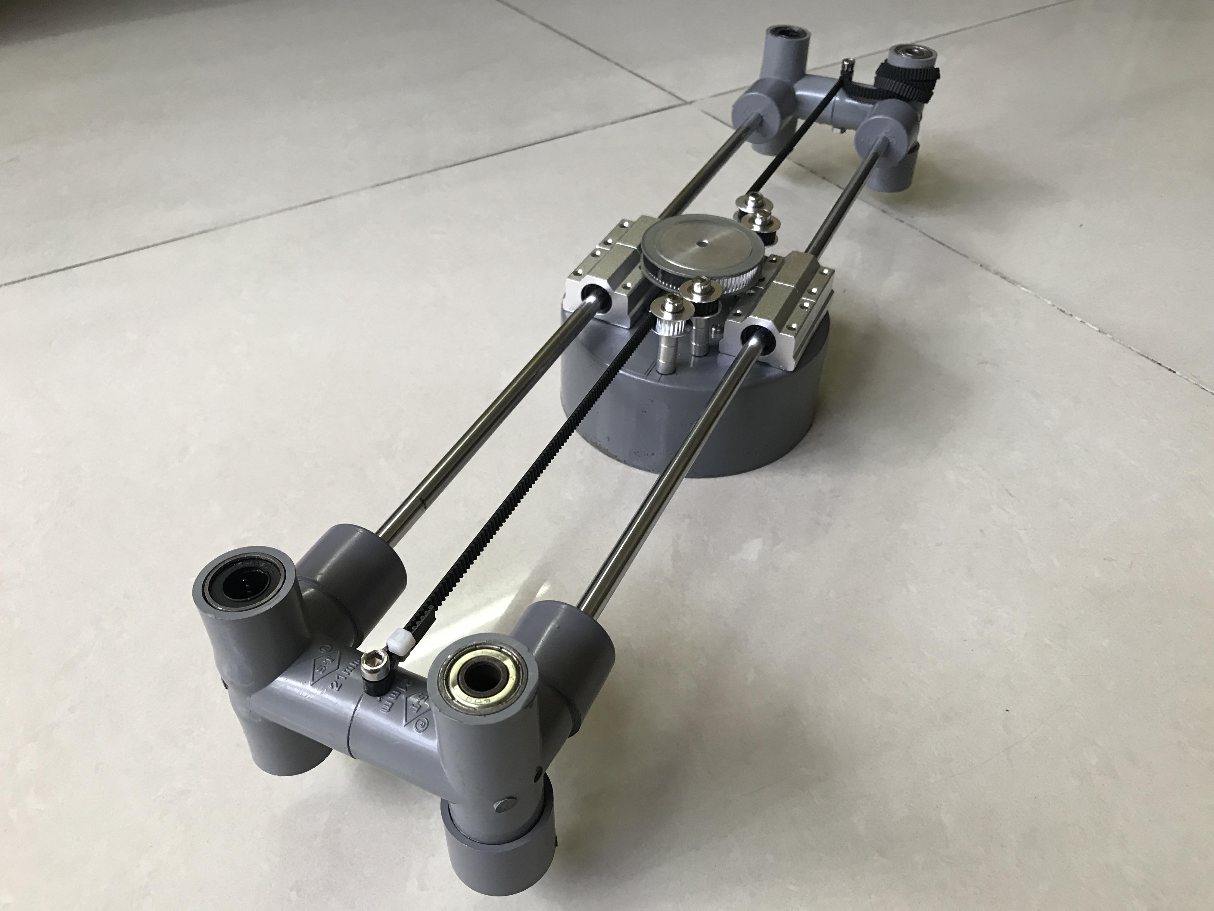
⦾ I installed X stepper motor with 80 teeth pulley on the PVC endcap Ø114mm. I liked the idea of fixing belt with moving stepper motor. So each side of 80 teeth pulley, I mounted one 20 teeth idler pulley and one toothless idler pulley. Two 20 teeth pulleys (located outside) were symmetrically aligned with the 80-tooth pulley across the center line.They are arranged as shown below.

⦾ 4pcs x SC8UU ball bearings were also mounted on this endcap for guiding X axis linear motion through 8mm round shafts, length 500mm.

⦾ I assembled this PVC endcap into the Z left and right part that made above. Then I threaded a timing belt through the pulleys and fixed it at both ends with 5mm bolts.

⦾ When operating, the X axis is in the direction shown below, with the stepper motor's bottom facing up and the belt system below. The X-axis stepper motor was fully enclosed in the PVC endcap by this way.

⦾Honestly, I didn't know if it would worked smoothly or not so I had to try it, and then proceed to the next steps.

⦾ Here is the test result:

Step 3: Frame Assembly
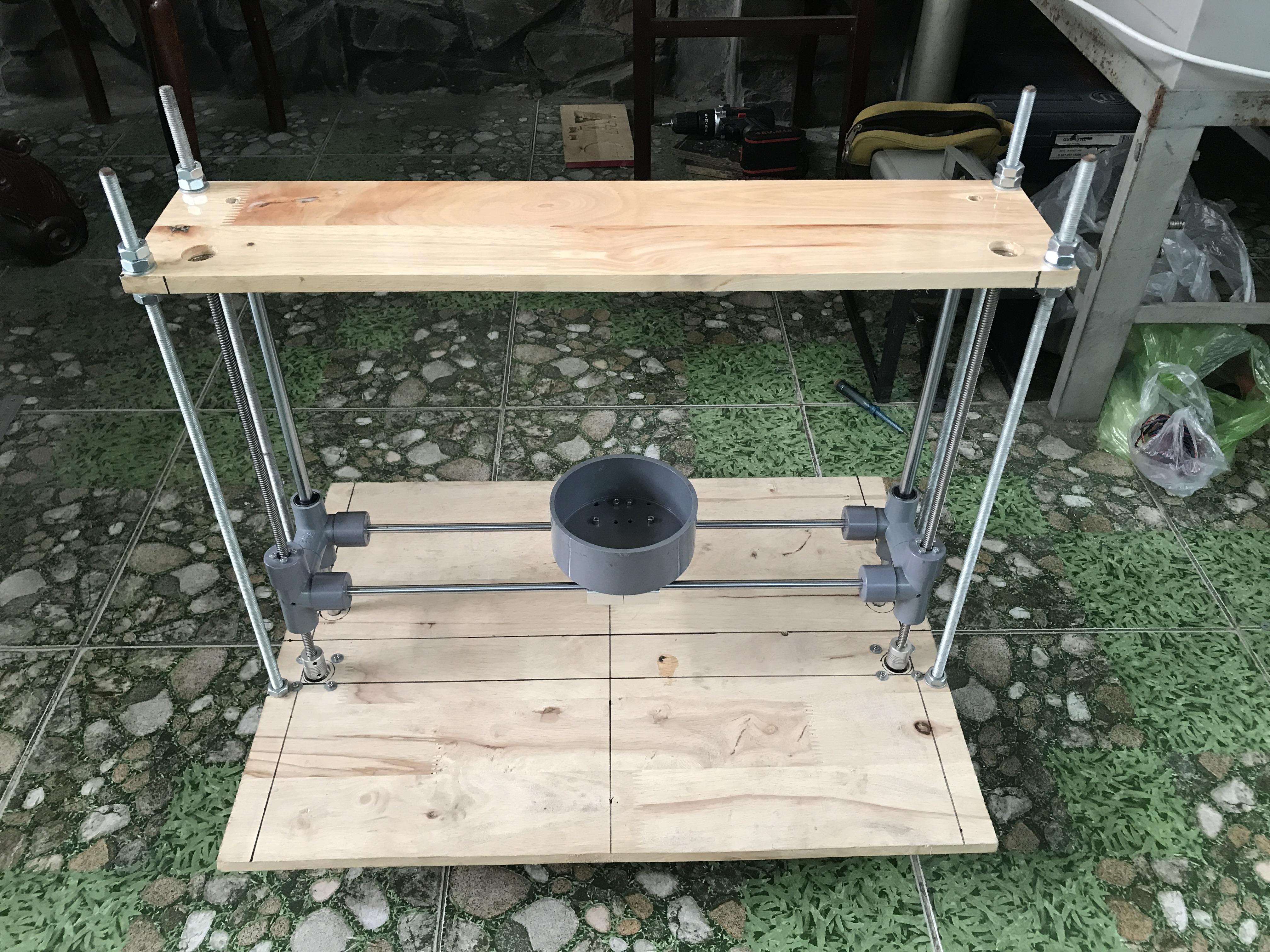
⦾ I carefully measured the XZ part assembled in previous step, marked then drilled 4 big holes on the wodden plate size 600x500x12mm for T8 lead screws and round shaft Ø12mm. Two Z stepper motors were mounted under the wooden plate and connected to lead screw by flexible couplings.

⦾ I tested and aligned by rotating the lead screws by hand.

⦾ A wodden plate size 600x130x12mm was mounted on the top of frame. Two flanged shielded bearings were also installed to prevent lead screws from wobbling.

⦾ Because I used step drill bit so when the small diameter was finished drilling, it will move to the next diameter step. Since wood thickness is 12mm, and each step of drill bit has a depth of 4mm, so 3 steps of the drill bit were drilled into the wood. To fix the shaft 12mm to the wood plate, I drilled 3 steps of drill bit as follow: 12mm, 10.5mm and 9mm.

⦾ I installed this wood plate on the top of 3D printer frame, it was fixed via 4 threaded rods diameter 10mm and 2 shafts diameter 12mm.

Step 4: Y Axis Assembly
⦾ 4pcs x SC8UU ball bearings were mounted on the wooden plate 500x450mm for guiding Y axis linear motion through 8mm round shafts, length 500mm.

⦾ Y stepper motor was install at bottom wooden plate. It drives Y-carriage via timing belt and 20 teeth pulley.

⦾ Opposite the Y stepper motor is 20 teeth idler pulley.

⦾ The Y carriage timing belt was fixed by 2pcs x M5 bolts and cable ties.

⦾ Heatbed 214x214mm 12V/24V Dual Power MK2B was installed on the Y carriage. My printer can be reach a build volume about 400 x 350 x 220mm but it was limited to 200 x 200 x 200mm due to heated bed size.

Step 5:
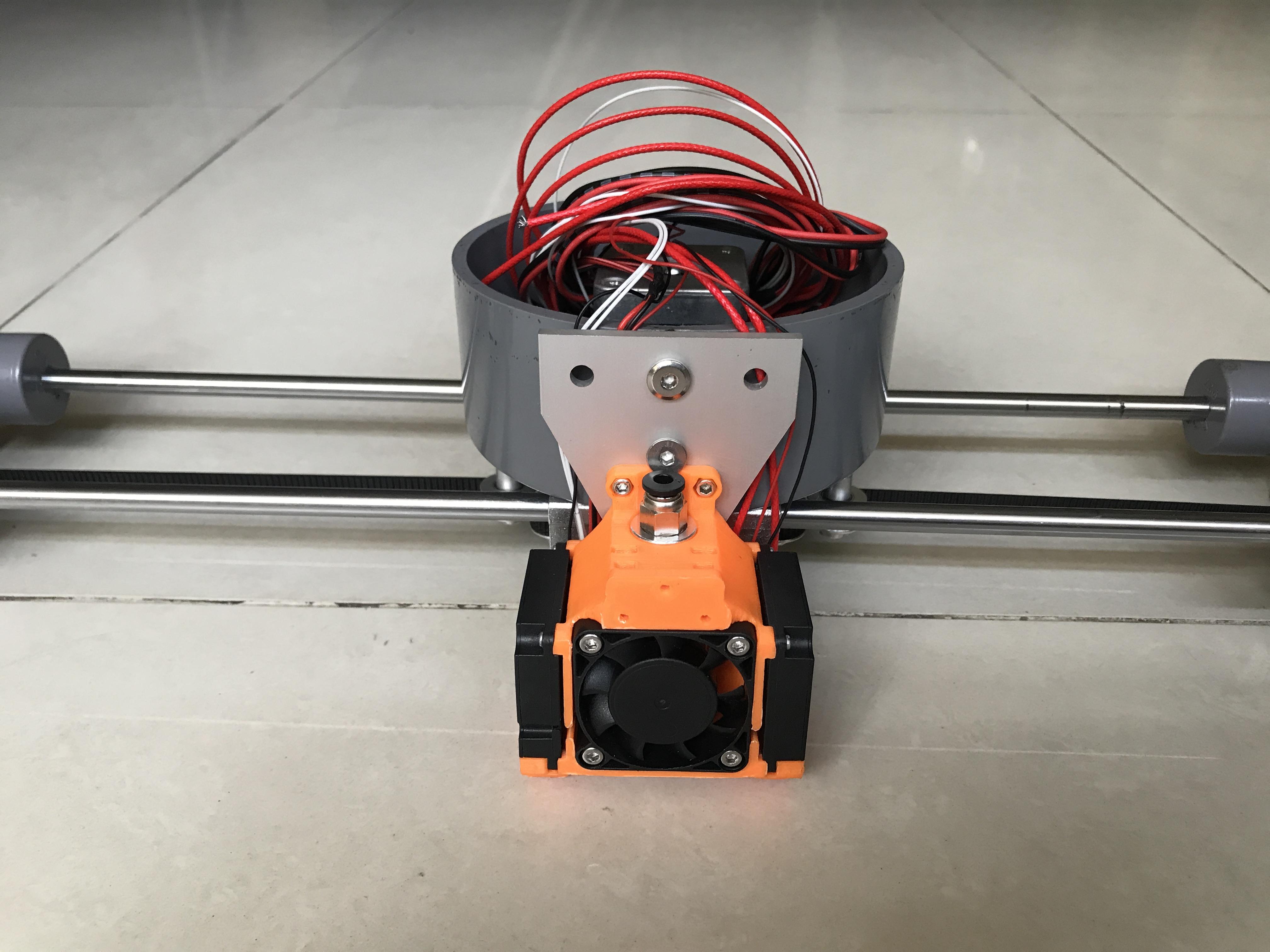
⦾ I originally planned to use a Bowen Print J-head Hot End and it comes equipped with one cooling fan bracket. We can do this way if we don't have 3D printer at home. In the below picture, I made a support to attach this hotend to PVC endcap of X axis.

⦾ But I ended up choosing another hotend that I printed for my Sapphire Plus SP-5 printer that is currently unused. This hotend mounting design and detail information is available at Thingiverse link below:
TwoTrees Sapphire Plus/Pro E3D V6, Dragon Mount "The Mint Mount"
T Shape Joint Plate (Fit 2020 series Aluminum extrusion) was used to connect between hotend printed part and PVC endcap.

⦾ The cables of hotend heater, thermistor, cooling fans were pre-connected.

⦾ During installation, I had to checked and adjusted so that the hotend nozzle tip should be located lower than the pulleys and timing belt.

⦾ Extruder stepper motor, LCD 2004 and filament filament spool holder were mounted on the top wood plate. I made this spool holder from PVC pipe fittings Ø42mm and Ø60mm.

Step 6: Endstops Assembly
⦾ The X-Endstop was mounted on the acrylic plate and then fitted to XZ left part.

⦾ The Y-Endstop was located at bottom wood plate.

⦾ The Z-Endstop would be adjusted up or down during calibrating & operating so I drilled 2 holes diameter 10mm on the acrylic support for this purpose.

⦾ I mounted the Z-Endstop support to thread rods. Z-Endsop could be easily adjusted up/down or fixed by 4pcs x M10 bolts as shown below.

Step 7: PSU Assembly
⦾ I had a power supply from my broken desktop, nameplate AcBel CE2 400W. It has dual channel outputs for 12V level voltage. So I had a chance to make it useful.

⦾ Detail information of AcBel CE2 400W is as picture below. The Power Supply Unit (PSU) needs a cable connection to the motherboard to be controlled to turn on/off. When we press the power button on our computer case, it connects the green wire to a ground - black wire, telling the PSU to turn on. To test PSU temporarily, I simply connected green wire to black wire at 20 pin connectors. Later when I put my 3D printer into operation, I would use a button to turn on/off the power.

⦾ I assembled the PVC pipe fittings (including: three and four way PVC tees) into a frame and mounted this PSU inside it. This frame was fitted under the bottom wood plate later.

⦾ I only left two pairs of yellow - black wires (12V power supply to RAMPS 1.6) and green - black wires (to On/Off button). I have tied up the rest of wires neatly.
Step 8: Controller and Cabling
⦾ I reused one broken stainless steel flexible hose pipe in my restroom for heatbed and hotend cable covers.

⦾ A flexible hose has one outer tube made of stainless steel and one inner pipe (black color). I used outer tube for hotend cable cover and inner pipe for heatbed cable cover.

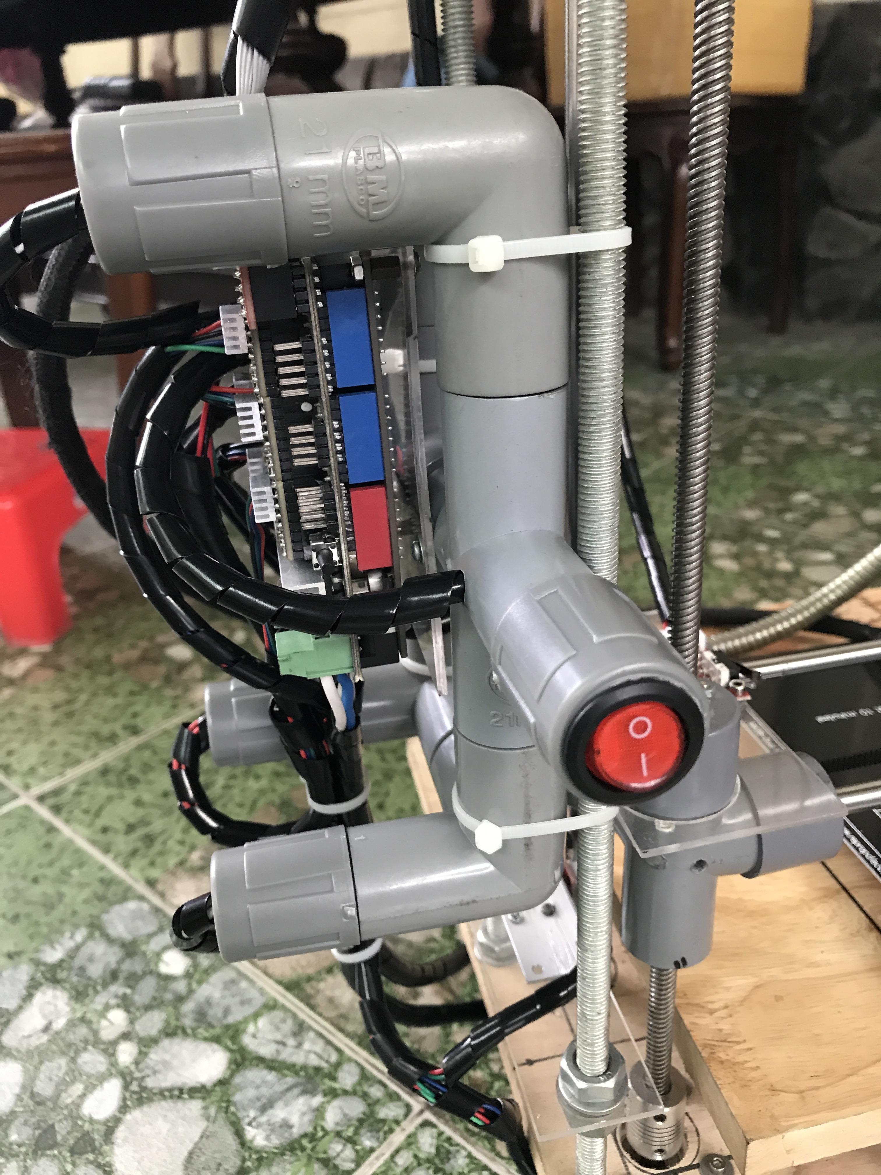
⦾ Arduino Mega 2560 and RAMPS 1.6 were mounted on the support made of PVC fittings. All wires were covered by black cable spiral wraps.

⦾ I've fitted a button to turn the power supply on/off as explained on the previous step.

⦾ I connected a PTFE Teflon tube from extruder stepper motor to the hotend.

⦾ It also looks okay, not mess at all.

Step 9: Marlin Firmware
Marlin firmware is available at: https://github.com/MarlinFirmware/Marlin/releases
I downloaded & installed Marlin firmware version 2.1.2 to Arduino Mega 2560 by Arduino IDE.
Parameter settings in "Configuration.h" for my 3D Printer is shown as follows:
⦾ Motherboard
// Choose the name from boards.h that matches your setup
#ifndef MOTHERBOARD
  #define MOTHERBOARD BOARD_RAMPS_14_EFB
#endif
⦾ Extruder
// This defines the number of extruders
// :[0, 1, 2, 3, 4, 5, 6, 7, 8]
#define EXTRUDERS 1
// Generally expected filament diameter (1.75, 2.85, 3.0, ...). Used for Volumetric, Filament Width Sensor, etc.
#define DEFAULT_NOMINAL_FILAMENT_DIA 1.75
⦾ Thermal Settings
#define TEMP_SENSOR_0 1
#define TEMP_SENSOR_1 0
#define TEMP_SENSOR_2 0
#define TEMP_SENSOR_3 0
#define TEMP_SENSOR_4 0
#define TEMP_SENSOR_5 0
#define TEMP_SENSOR_6 0
#define TEMP_SENSOR_7 0
#define TEMP_SENSOR_BED 1
#define TEMP_SENSOR_PROBE 0
#define TEMP_SENSOR_CHAMBER 0
#define TEMP_SENSOR_COOLER 0
#define TEMP_SENSOR_BOARD 0
#define TEMP_SENSOR_REDUNDANT 0
⦾ Endstop Settings
// Specify here all the endstop connectors that are connected to any endstop or probe.
// Almost all printers will be using one per axis. Probes will use one or more of the
// extra connectors. Leave undefined any used for non-endstop and non-probe purposes.
#define USE_XMIN_PLUG
#define USE_YMIN_PLUG
#define USE_ZMIN_PLUG

// Mechanical endstop with COM to ground and NC to Signal uses "false" here (most common setup).
#define X_MIN_ENDSTOP_INVERTING true // Set to true to invert the logic of the endstop.
#define Y_MIN_ENDSTOP_INVERTING true // Set to true to invert the logic of the endstop.
#define Z_MIN_ENDSTOP_INVERTING true // Set to true to invert the logic of the endstop.
⦾ Stepper Drivers
#define X_DRIVER_TYPE  DRV8825
#define Y_DRIVER_TYPE  DRV8825
#define Z_DRIVER_TYPE  DRV8825
#define Z2_DRIVER_TYPE DRV8825
#define E0_DRIVER_TYPE DRV8825
⦾ Movement Settings
To calculate the steps per millimeter for my 3D printer axes, I refered to this site:
https://blog.prusa3d.com/calculator_3416
- For X axis, I used the fixed belt driven systems so X step/mm are: 40 step/mm (Pulley tooth count = 80, Microstepping = 1/32).
- For Y axis, I used the normal belt driven systems so Y step/mm are: 80 step/mm (Pulley tooth count = 20, Microstepping = 1/16).
- For Z axis, I use the leadscrew driven system so parameter Z step/mm is: 400 step/mm (microstepping = 1/4).
- For Extruder, the step/mm is: 142 step/mm after calibration.
/**
 * Default Axis Steps Per Unit (steps/mm)
 * Override with M92
 *                                      X, Y, Z [, I [, J [, K]]], E0 [, E1[, E2...]]
 */
#define DEFAULT_AXIS_STEPS_PER_UNIT   { 40, 80, 400, 180 }

/**
 * Default Max Feed Rate (mm/s)
 * Override with M203
 *                                      X, Y, Z [, I [, J [, K]]], E0 [, E1[, E2...]]
 */
#define DEFAULT_MAX_FEEDRATE          { 100, 100, 5, 25 }

//#define LIMITED_MAX_FR_EDITING        // Limit edit via M203 or LCD to DEFAULT_MAX_FEEDRATE * 2
#if ENABLED(LIMITED_MAX_FR_EDITING)
  #define MAX_FEEDRATE_EDIT_VALUES    { 600, 600, 10, 50 } // ...or, set your own edit limits
#endif

/**
 * Default Max Acceleration (change/s) change = mm/s
 * (Maximum start speed for accelerated moves)
 * Override with M201
 *                                      X, Y, Z [, I [, J [, K]]], E0 [, E1[, E2...]]
 */
#define DEFAULT_MAX_ACCELERATION      { 1000, 1000, 50, 5000 }

//#define LIMITED_MAX_ACCEL_EDITING     // Limit edit via M201 or LCD to DEFAULT_MAX_ACCELERATION * 2
#if ENABLED(LIMITED_MAX_ACCEL_EDITING)
  #define MAX_ACCEL_EDIT_VALUES       { 6000, 6000, 200, 20000 } // ...or, set your own edit limits
#endif
⦾ LCD and SD support
#define LCD_LANGUAGE en

#define DISPLAY_CHARSET_HD44780 JAPANESE

#define LCD_INFO_SCREEN_STYLE 0

#define SDSUPPORT

#define SD_CHECK_AND_RETRY

//  Set this option if CLOCKWISE causes values to DECREASE
#define REVERSE_ENCODER_DIRECTION

#define SPEAKER
⦾ LCD / Controller Selection
// RepRapDiscount Smart Controller.
// https://reprap.org/wiki/RepRapDiscount_Smart_Controller
//
// Note: Usually sold with a white PCB.
//
#define REPRAP_DISCOUNT_SMART_CONTROLLER
Step 10: Ultimaker Cura Settings
Open Ultimaker Cura ‣ Settings ‣ Printer ‣ Add Printer ‣ Add a none-networked printer ‣ Creality3D ‣ Creality Ender-3 Pro.

Click Add ‣ Window "Machine settings" appears ‣ Go to Tab "Printer", it shows some critical set-up parameters for original Ender-3 Pro and I can customize some parameters for my DIY printer.
We pay attention on the codes in "Start G-code" and "End G-code" windows that make my DIY Printer working as same as Ender-3 Pro when it start and end excuting a G-code file.

⦾ Start G-code
; Ender 3 Custom Start G-code

G92 E0 ; Reset Extruder

G28 ; Home all axes

G1 Z2.0 F3000 ; Move Z Axis up little to prevent scratching of Heat Bed

G1 X0.1 Y20 Z0.3 F5000.0 ; Move to start position

G1 X0.1 Y200.0 Z0.3 F1500.0 E15 ; Draw the first line

G1 X0.4 Y200.0 Z0.3 F5000.0 ; Move to side a little

G1 X0.4 Y20 Z0.3 F1500.0 E30 ; Draw the second line

G92 E0 ; Reset Extruder

G1 Z2.0 F3000 ; Move Z Axis up little to prevent scratching of Heat Bed

G1 X5 Y20 Z0.3 F5000.0 ; Move over to prevent blob squish
⦾ End G-code
G91 ;Relative positioning

G1 E-2 F2700 ;Retract a bit

G1 E-2 Z0.2 F2400 ;Retract and raise Z

G1 X5 Y5 F3000 ;Wipe out

G1 Z10 ;Raise Z more

G90 ;Absolute positioning

G1 X0 Y{machine_depth} ;Present print

M106 S0 ;Turn-off fan

M104 S0 ;Turn-off hotend

M140 S0 ;Turn-off bed

M84 X Y E ;Disable all steppers but Z
Step 11: Calibration
⦾ After powering on the 3D printer, I moved the X, Y, Z axes in the forward and reverse directions, checking if the movement was correct, and did correction.

⦾ We can refer to the following website to understand how to calibrate step/mm of each axis, as well as, E-Steps:
https://all3dp.com/2/how-to-calibrate-a-3d-printer-simply-explained/
https://help.prusa3d.com/article/extrusion-multiplier-calibration_2257
⦾ After calibrating XYZ axes & levelling heat bed, I set my 3D printer to home position by "Auto Home" function. It can check if the endstops're working properly.

⦾ I can power on or off the power supply by a button mounting on the 3D printer frame.

Step 12: Conclusion
My printer is still lack of 2 parts: one filament roll and heated bed sticker before I can print the samples. Although my 3D printer run smoothly in case of no-filament test, but, it probably need to be reinforced, extended or improved. I'll update later.
Thank you for reading my work!!!
Please LIKE, SHARE & SUBSCRIBE to my Youtube channel!

Participated in the
Repair and Reuse Contest


