Introduction: RS485 – ARDUINO AND INDUSTRIAL DISTANCE SENSOR
I have in my hand a distance laser sensor with high precision and speed. It is used in industrial environments for object positioning or detection applications. According to technical documents, I found it can communicate with other devices via RS485. I spent the weekend to learn it and find ways to communicate with cheap CPU - Arduino. And finally, I succeeded in reading data from it and displaying the distance value on the led screen.
And I'm willing to share this test with you. Let's start with the video below:
Step 1: B.O.M
Main components include:
- Arduino Mega 2560. (Option to check the RS485 communication because it has multiple serial ports. We can use Arduino Mega 2560 to print the value on Arduino IDE for program debugging).
- Module RS-485. It is very cheap, about $0.4 on AliExpress.
- LOL Shield Matrix. For LoLShiled, I did it by myself at home. You can refer to PCB design at: https://github.com/jprodgers/LoLshield & make one for yourself.
- Power Supply 5VDC and 24VDC. For me, I used a power supply PS 307 from Siemens.
Step 2: CIRCUIT DIAGRAM AND ASSEMBLY
The circuit schematic is shown on picture above.
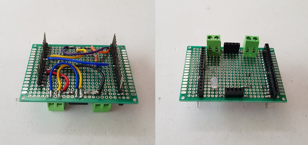
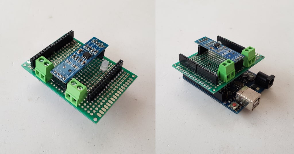
My idea is to read distance data and display this value on LoLShield. To do this, I had to turn the RS-485 module into a Shield to plug it on the Arduino and then Lolshield matrix will be plugged on the top.
- Soldering RS-485 Shield:
RS-485 Shield after soldering with male header at bottom and female header on the top.

Installing Module RS-485 on the the shield and plug this shield on Arduino Uno.

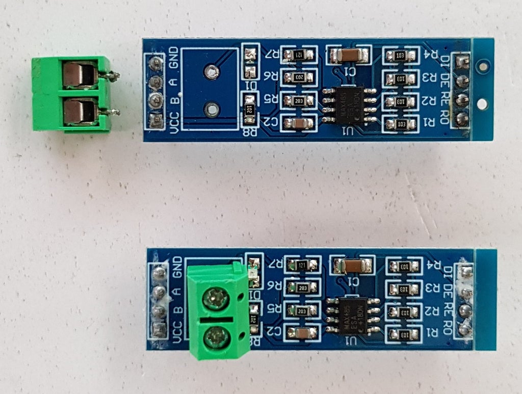
Note: I had to removed 2 pins female header from original RS485 module and soldered it on the shield otherwise it is too high and LoLShield can't plug on this shield.

- LoLShield:
For LoLShiled, I did it by myself. It is not easy for etching a double sided copper clad PCB board at home. You can refer to PCB design at: https://github.com/jprodgers/LoLshield & make one for yourself.

- Plugging 2 shields on Arduino :

- Make a protection box with some open holes for wires connection and programming cable:

- Connecting circuit board to laser sensor and power supply:

Note: The 0V/ GND of power supply 5VDC and 24VDC are connected together.
Step 3: DISTANCE LASER SENSOR - TECHNICAL SPEC
The laser distance sensors S80 SERIES (DATALOGIC) with time of flight measurement are suitable for long distance measurements offering constant performances on the entire range. In my case, this S80-Y0 sensors function as proximity on respectively a 0.3 - 4 m distance, or from 0.3 to 7 m with scalable range.
About RS485 serial interface:
The serial communication parameters are: 9600 baud, no parity, 8 data bits, 1 stop bit. It is matching with serial interface "SERIAL_8N1" in "HardwareSerial" Arduino's library.
The SYNC input is used to determine the communication direction, and in particular if low (active) direction Sensor->Arduino, if high (passive) Arduino->Sensor. You can review the diagram in Step 2, the SYNC signal is connected to 0V/GND to active receive mode.

With SYNC active, the sensor continuously transmits the detected distance value (with a precision of 12bit) by means of a binary data format. 2 byte are used; one with bit 0 at logic level 1 identifies the more important byte.

Step 4: DISPLAY EXPLANATION
The LoL Shield is a 9x14 charlieplexing LED matrix for the Arduino and this design DOESN'T include current limiting resistors. The LEDs are individually addressable, so we can use it to display information in a 9×14 grid.
The LoL Shield leaves D0 (Rx), D1 (Tx) and analog pins A0 to A5 free for inputs. For detail, let see picture below for LoLShield pin usage:

From my schematic, we can see:
- D0 (Rx) and D1 (Tx): connect to RO and DI of RS485 module.
- A0: connecting to Led indicator.
- A1: connecting to DE/RE of RS485 module.
- D2 to D13: connecting to LoLShield.
To show distance value with a precision of 12bit (4 digits number), I used a small font size 3x5 for digits as below:

LOL Shield only has 14 columns so it can't display all 4 digits so I just show 3 digits in 3x5 small font above and luckily LoL Shield has 9 rows and it can display the number of units according to the number of leds from 0 to 9. Let's see the below picture to clarify my explanation:

Step 5: PROGRAMMING
The laser sensor will send the distance value in range 250mm to 4020mm to Arduino as explained below:
- Distance Value < 250 - Low Limit. Print "LL" on the LoLShield screen.
- 250<= Distance Value <= 4020 - In Measuring Range. Print the distance on the LoLShield screen.
- Distance Value > 4020 - High Limit. Print "HH" on the LoLShield screen.
- And in case, the RS485 is not available, I print "FF" on the LoLShield screen.
We can double check with the distance value shown on the small 4-digit display attached on the Laser Sensor.
The full code of this project is posted in my GitHub: https://github.com/tuenhidiy/RS485-ARDUINO-AND-IND...
#include <avr pgmspace.h>
#include "Charliplexing.h"
#include "Myfont.h"
#include "Font.h"
#include <Hardwareserial.h>
#define BAUDRATE 9600

// Font 3x5 for the digits
int digits[][15] = {
   {1,1,1,1,0,1,1,0,1,1,0,1,1,1,1}
  ,{0,0,1,0,0,1,0,0,1,0,0,1,0,0,1}
  ,{1,1,1,0,0,1,1,1,1,1,0,0,1,1,1}
  ,{1,1,1,0,0,1,1,1,1,0,0,1,1,1,1}
  ,{1,0,1,1,0,1,1,1,1,0,0,1,0,0,1}
  ,{1,1,1,1,0,0,1,1,1,0,0,1,1,1,1}
  ,{1,0,0,1,0,0,1,1,1,1,0,1,1,1,1}
  ,{1,1,1,0,0,1,0,0,1,0,0,1,0,0,1}
  ,{1,1,1,1,0,1,1,1,1,1,0,1,1,1,1}
  ,{1,1,1,1,0,1,1,1,1,0,0,1,0,0,1}
};

void setup()
{
  LedSign::Init(DOUBLE_BUFFER);
  Serial.begin(BAUDRATE,SERIAL_8N1);  //Using Serial port with 9600 baudrate, non-parity, 8 data bits, 1 stop bit.
  pinMode(A1, OUTPUT);                //DE/RE Controling pin of RS-485
  pinMode(A0, OUTPUT);                //LED Indicator
}
void loop()
{
  byte getdata[2];
  byte High_Byte;
  byte Low_Byte;
  unsigned int wordx;
  boolean D7=0;
  // Enable Received
  digitalWrite(A1,LOW);     //DE/RE=LOW Receive Enabled
  // Receive data from Laser Sensor
  if(Serial.available())
    {
      digitalWrite(A0,HIGH);//LED
      for (byte i=0; i<2; i++)
        {
          getdata[i]=Serial.read();
          delay(15);
        }
    }
  else
    {
    digitalWrite(A0,LOW);   //LED
    LedSign::Clear();
    Myfont::Draw(0, 'F');
    Myfont::Draw(9, 'F');
    delay(1000);
    LedSign::Clear();
    }
  // Check the correct data
if(Serial.available())
  {
  if (bitRead(getdata[0],0)==0)
    {
      Low_Byte=getdata[0];
    }
  if (bitRead(getdata[1],0)==1)
    {
      High_Byte=getdata[1];
    }

  // Two bytes conversion
  // | 0 0 D11 D10 D9 D8 D7 1 | | D6 D5 D4 D3 D2 D1 D01 0 |
  // |        High_Byte       | |       Low_Byte          |

  D7 = bitRead(High_Byte,1);
  Low_Byte=(Low_Byte & 0xFE) >> 1;
  bitWrite(Low_Byte, 7, D7);
  High_Byte=(High_Byte & 0x3F) >> 2;
  wordx = (High_Byte << 8) | Low_Byte;

// Print all digits on LoLShield screeen.
  if(wordx < 250)
    {
      LedSign::Clear();
      Myfont::Draw(0, 'L');
      Myfont::Draw(9, 'L');
    }
  else if ((wordx >= 250)& (wordx <= 4020))
  {
  LedSign::Clear();
  // first digit - thousand
  for (int i=0; i<15; i++)
  {
    LedSign::Set((i % 3)+ 0,(i/3)+2, digits[(wordx/1000) % 10][i]);
  }
  // second digit - hundred
  for (int i=0; i<15; i++)
    {
      LedSign::Set((i % 3)+ 4,(i/3)+2, digits[(wordx/ 100) % 10][i]);
    }
  // third digit - Ten
  for (int i=0; i<15; i++)
    {
      LedSign::Set((i % 3)+ 8,(i/3)+2, digits[(wordx/10) %10][i]);
    }
  // fourth digit - Unit
  for (int y=0; y < 9; y++)
    {
      if (y < (wordx %10))
        {
          LedSign::Set(13, y, 1);        // set the LED on
        }
      else
        {
          LedSign::Set(13, y, 0);       // set the LED off
        }
    }
  }
  else
  {
    LedSign::Clear();
    Myfont::Draw(0, 'H');
    Myfont::Draw(9, 'H');
  }
}
  LedSign::Flip();
}
Step 6: FINISH
My hobby is always finding ways to connect Arduino to PLCs or sensors that are being used in industrial environments. It would be great if we could read / write/ integrate the low cost CPUs or circuits into industrial automation systems.
Maybe a bit late but please vote for me in "SENSORS CONTEST".
THANK FOR YOUR WATCHING!

Runner Up in the
Sensors Contest


