Introduction: Robot Brains
To make decisions, a robot uses a computer or microcontroller. For those unfamiliar, a microcontroller is basically an electronic component which can do three things. It can interpret inputs from the physical world, process this information, and control output devices in the physical world. In a basic sense, a microcontroller can read sensors, make decisions, and control lights, speakers, and motors.
By being able to both sense and respond to the world, you can create a feedback loop between the output and the input. In other words, you can create robots and devices which are truly interactive. Another way to think about this is that the robots can pay attention to what is happening around them, make decisions using the Arduino, and then respond meaningfully to it. In this way, they behave a bit like most other sentient creatures.
Step 1: The Arduino
The Arduino is a very common type of microcontroller. What sets the Arduino apart from other microcontrollers is that is is easy to use, well documented, and has a vast online community of people using it. This means that no matter what may go wrong, you can likely find a documented solution online or someone willing to help you. This is extremely beneficial when getting started.
There are a number of different types of Arduinos, but for this class we will be using an Arduino Uno. This is currently the most ubiquitous version of Arduino microcontrollers. By the time this lesson is over, you will have a brief understanding of how to use the board, but you will by no means be an expert.
While the Arduino has a lot of features, there are a few you have to pay attention to. There is a USB port which is used for programming. There is a power socket that is used for powering the Arduino when not connected to your computer. There are also two rows of female sockets along the edge of the board. Each one of these little holes connects to something different on the board, and performs a different function. They should all be labeled fairly well to indicate what they are.
If and when you get confused, you can find a much more in-depth overview by checking out the Arduino Class.
Step 2: Plug It In.
To power up the board simply connect it to your computer with a USB-A to USB-B cable. This is basically a standard USB cable that something like a computer printer would use.
Step 3: Programming the Arduino
To program the Arduino we will be using the Arduino IDE (integrated development environment). The most current version of the software can be downloaded for free from the Arduino site or used directly on the internet (soon).
Step 4: A Note About Programming
The most important thing to know about programming is to fake it untill you make it. Basically, you don't actually need to know how to program to work with code. There is a ton of example code already out there. You just need to understand its basic structure. Once you got this, it is just a matter of finding and tweaking code which already exists. If you just stick with this approach, keep an open mind, and a fearless spirit, eventually you will learn to program for real-like.
However, it is not entirely a free-for-all. There are a few things you need to understand. Please bear with me while I drop some very basic coding knowledge on you. BAM!
Step 5: Syntax
Every programming language has a syntax for how the code needs to be formatted. That is basically the equivalent of knowing proper grammar.
For instance, most expressions in programming end with a semicolon -
like so; This is a bit like writing a period at the end of the sentence.
If you write an essay without periods you will confuse the heck out of
the reader. Likewise, if you write an Arduino program without syntax,
you will confuse the heck out of the compiler. The compiler interprets
the code and is a bit like the reader of an essay in our analogy.
If
you are ever getting strange errors and can't tell why, chances are you
have broken one of the rules of syntax (i.e. formatting).
Step 6: Code Expressions
When reading and writing code you will encounter some basic building blocks just like you would in any other language. For instance, English has nouns, adjectives, and verbs. These components are then structured into sentences. Programming in turn has constants, variables and operators. These are then structured into functions.
Here are some basic definitions of common programming components:
Constants are terms which are defined once and do not change.
Variables are terms which are placeholders for other values and can change.
Operators are terms which perform an action, which is typically some form of math or logical comparison between values.
Functions are a structured collection of constants, operators and variables. Every time a function is called, it reads through and executes the same specific action routine.
Step 7: Program Structure
Once you have mastered the components of English grammar and have begun writing sentences, the next logical step is to write a composition such as an essay. Just as an essay has a structure with an opening paragraph, body text, and a closing paragraph, so does an Arduino program. However, an Arduino program's structure is a little bit different.
A typical program is laid out as follows:
//####################
//###  THE HEADER  ###
//####################

// The header explains to you as a human what the program is doing
// It is not processed by the compiler
// Also note that anything preceeded by two slashes like so '//'
// is considered a comment and not processed by the compiler.
// Comments explain to you what is happening in the code.


//#####################
//###  DEFINITIONS  ###
//#####################

// Definitions are things that we want to establish globally throughout the code.
// We do this first thing before the code starts.
// It only happens once when the code runs.

// Libraries are often required to add additional functionality to the Arduino software.
// One example we will be using a lot is the servo library.
// By adding the servo library we get servo-specific commands which makes life easier.
#include <libraries.h>


// We can also define variables and constants
// that we want to establish globally throughout the code.
// There are different types of variables and constants
// Learn more here under 'constant' and 'data types':
// http://www.arduino.cc/en/Reference/HomePage

// For instance, we can establish an intenger variable
int definition1;

// We can also both establish a long variable and give it a starting value.
long definition2 = 3000;

// We can also name something a constant, and give it a value which won't change
const thisIsAConstant = 2;


//################
//###  SETUP  ###
//################

void setup() {

  // The setup code goes here.
  // Like definitions it only runs once.
  // The difference is that in the setup you include things you want to do,
  // not things you want to define.

  // For instance, you may want to move a servo motor to it's default position

  // Or engage the Serial Monitor for debugging your code

  // Or blink an LED test pattern to let you know the application has started

}


//###################
//###  MAIN LOOP  ###
//###################

void loop() {

  // Anything put here will run over and over.
  // This is where the bulk of your code should live.
  // The Arduino will loop through whatever is here indefinately until it runs out of power.

}

//##############################
//###  ADDITIONAL FUNCTIONS  ###
//##############################

// If you write your own custom functions, they would be placed down here below the main loop.
// You can call these functions from either the setup or main loop.
// They are useful if you need to do a particular set of things frequently
// Instead of writing it over, and over, you can just call the function

void yourcustomfunction(){

  // Here is where you write your custom function

  // It can be a particular routine such as configuring motors
  // to drive forwards, backwards, right or left.

  // Or it can be a routine to check a sensor.

}

//####################
//###  THAT'S ALL  ###
//####################

// Don't worry. This is all super-confusing at first.
// This will make more sense as you do it.
The compiler typically reads from left to right from one line to the next. Well - for the most part. There are a few key differences from the way that a normal person that are crucial to understand.
A good way to think about a computer program is a bit like a choose your own adventure story. The compiler reads the story like it would any other, but when the compiler reads a function, instead of reading the next line, it jumps to where that function lives and reads it line by line instead. When it is done reading the function, it goes back to the next line in the code from where it left off. Also, functions can have other functions nested within them. So, a function, can lead to another function, to yet another function, before going back to the main routine.
If that in and of itself were not confusing, the program all reads down the page - to a point! And this is important to remember... When the compiler gets to the main loop(), whatever is contained within this loop is repeated over and over and over and over until the Arduino runs out of power. The main loop() is the endlessly repetative place where the meat of the code should live. Whatever you are trying to accomplish should exist in the main loop().
All of this is likely very confusing and foreign to you. That's okay. Learning the Arduino programming language is a bit like learning any language. It takes time to get the hang of it, and even then it takes a long time to be truly fluent.
To learn more about programming, a good place to start is Codecadamy.
Step 8: Run a Program
Running a program on the Arduino is dead simple.
To begin, you need to specify the type of board you are using. That is easy, select the "Arduino/Genuino Uno" option.
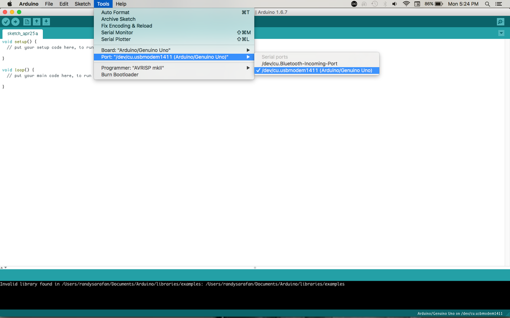
You also eneds to specify the port where the Arduino is found. That is a little bit trickier, but not too hard. Just select the option that looks like "/dev/cu.usbmodem [random numbers]"
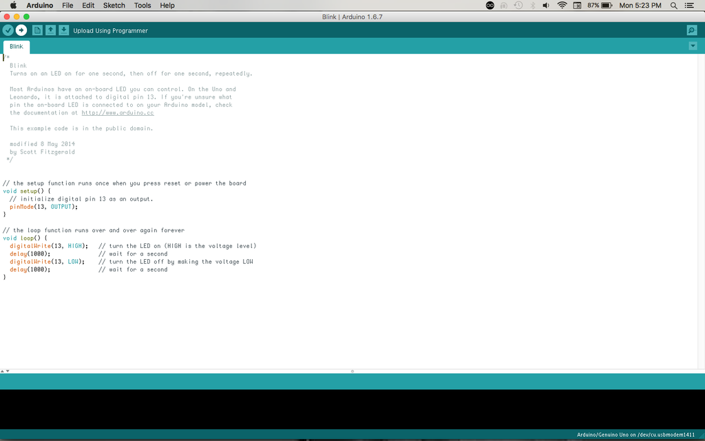
Open the Blink example from the Example 01.Basics menu. Then, find the upload button (this looks like right-pointing arrow) and press it. If everything is configured correctly, it should cause the LED on the Arduino board to blink steadily.
Try changing the number value within the delay functions and reupload the code. Notice that it changes the rate at which it blinks.
Now that you have got this down, let's try blinking an external LED not soldered directly to the Arduino board.
Step 9: All About Breadboards
When you need to prototype a circuit that connects to the Arduino, you should use a breadboard.
Breadboard are meant to make quick non-permananent connections between electronic components. They are covered in tiny socket holes which are connected in rows. The board itself is broken into four sections. There are two inner sections full of short horizontal rows, and two outer sections with longer vertical rows.
The inner sections are typically used for connecting components, and the outer sections are typically used as power bus lines. In other words, you can connect a battery to one of the outer lines and then power components on the inner section by connecting a wire to this section.
In the above graphic you can visually get a sense of how the rows on breadboards are electrically connected. The two inner sections have short horizontal rows repeated down the board. The two outer sections each have two long vertical rows. These are marked in red and blue and are meant to signify a row for power (red) and a row for ground (blue). Not all breadboards are marked with lines like this, but they are all laid out the same way.
For much more information about breadboard's check out this Breadboard Tutorial.
Step 10: A Quick Note on LEDs
Althought people think of LEDs as little light bulbs, they are actually quite different. LEDs are a type of electronic component called a diode. In fact, LED is an abbreviation for light emitting diode.
There is a lot to say about their unique status as a diode, but for our purposes the only thing that you need to know is that diodes only allow electricity to flow in one direction. They are what you would call 'polarized'. There is one leg that should always be connected to power and one that should be connected to ground. If you connect them backwards, power won't flow.
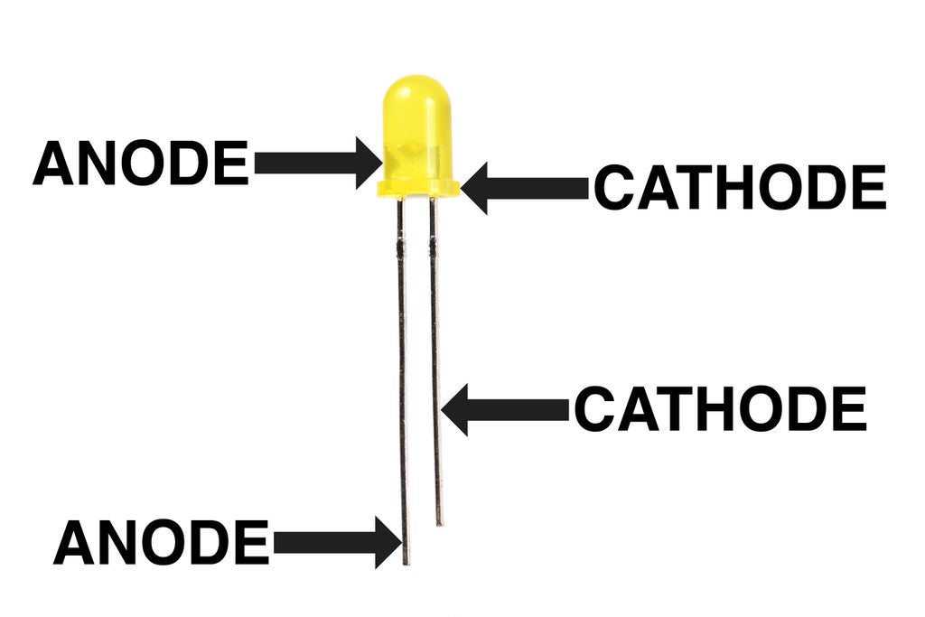
The leg which is connected to power is called the anode. The leg which is connected to ground is called the cathode. There are three ways to tell apart an LED's anode from its cathode.
1) The leg connected to the anode is typically longer than the one connected to the cathode.
2) The body of the LED typically has a flat spot on the cathode side.
3) If you look inside the LED, the little metal bit connected to the anode lead is much smaller than the cathode.
Step 11: Resistors
Resistors basically add resistance to a circuit. There are many reasons for doing this, but I don't have all day to explain.
Basically, we need a resistor in the circuit we are about to build because an LED offers no resistance. If we connect power through an LED without any resistance, then it is basically the same as creating a short circuit by connecting the power supply to ground. We add a resistor in series to the LED to use up some of the power and prevent a short circuit. If you want to know more, you can learn more about resistors and resistance in the Basic Electronics tutorial.
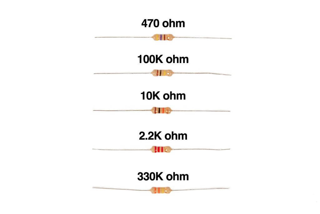
The only thing we need to know about resistors at this juncture is that even though they roughly look the same, they all have different values. You can tell how much resistance each one offers by reading the resistor codes marked upon them. Resistor codes are read from left to right towards the gold (or silver) band.
To begin, the easiest way to interpret the codes is to use an online graphical resistor calculator. Once you use this enough, you will begin to learn how to interpret them on your own without the calculator.
Step 12: Breadboard a Circuit
Insert an LED into a breadboard. Connect a 150 ohm resistor in series with the LED's cathode.
Using a black solid core wire, connect the opposite end of the resistor (the side not connected to the LED) to ground on the Arduino.
Using a red solid core wire, connect the LED's anode to digital pin 7 on the Arduino.
Step 13: Blink an External LED
You can blink an external LED by opening the Blink example code and changing this code and replacing all the number 13 to the number 7 whenever it shows up. By doing this, you are simply changing the digital pin that is being pulsed on and off from 13 to 7 in order to match the circuit you built on your breadboard.
Step 14: Fade an LED
Aside from blinking an LED, we can also make one fade. To do this we need to use a PWM pin. The PWM pins are special digital pins on the Arduino that allow for an analog-like output that simulates an output voltage between 0 and 5V. They are all labeled with a ~ in front of the pin number.
PWM stands for pulse width modulation. Put simply, PWM is toggling a pin on and off so fast that it gives the appearance of dimming the LED.
A dim LED glowing at 1/4 brightness means that the signal being sent to it is toggled off much more than it is toggled on. For instance, it is turned off 75% of the time and turned on 25% of the time. A brighter LED at 3/4 brightness is receiving a PWM signal that is the opposite. So it would be on 75% of the time and off 25%. The thing is, it is happening so fast, you don't see that it is being turned on and off, but only experience the LED as being slightly dim.
Anyhow, if you want to fade the LED, from the examples menu select:
03.Analog --> Fading
Once done, swap the wire connected from digital pin 7 to digital pin 9, and upload the code to your Arduino.
The LED should now fade in and out.
Step 15:
Once you have mastered blinking and fading LEDs, you can transfer this knowledge to controlling a motor. However, you cannot connect a motor directly to the Arduino pin for two reasons. First, the Arduino pin is only able to provide a little bit of current, and a motor is a current hog (especially when it starts and stops). Also, when a motor stops, it produces a current of opposite polarity to the one it is running at. This current is known to damage Arduino pins and stop them from working. Thus, building a buffer circuit is useful.
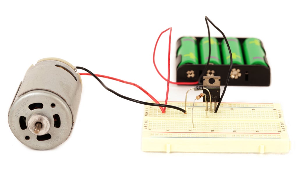
All you need to control a motor using an Arduino is a 2K resistor, an NPN transistor (TIP120 in this case), and a 1N4001 diode. The 2K resistor works to protect the Arduino pin, the transistor serves as a valve which lets more or less current flow through the motor. This is what turns the motor on and off, and controls its speed.
The diode is used as a buffer. When electricity flows through the motor, the diode does nothing. However, when the motor stops, the reverse current flows across the diode, and back through the motor. This protects the circuit from sudden voltage spikes.
If all of this sounds confusing, you can learn more about these basic components in my Electronics Class.
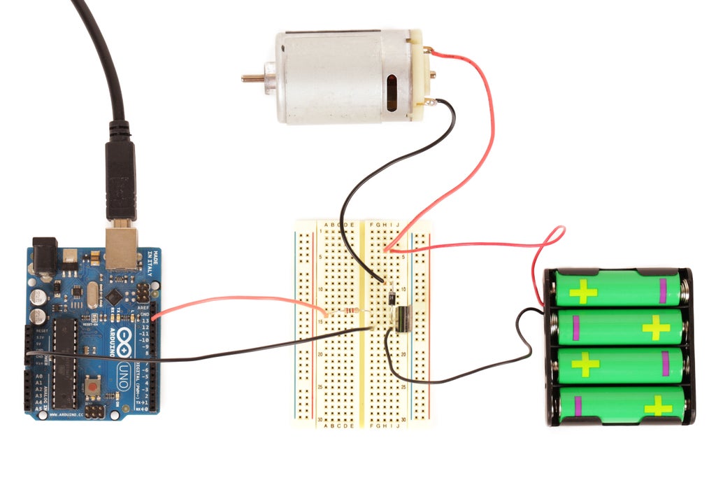
If you want to turn the motor on and off using the pictured circuit you need to make two more connections. First, connect the external battery pack's ground to the Arduino's ground pin. This is called "sharing ground" and is necessary for the circuit to work. Next, connect pin 13 from the Arduino to the 2K resistor connected to the transistors base. Once this is done, load the Blink example and upload it to the Arduino. Instead of blinking an LED, it will power on and off the motor.
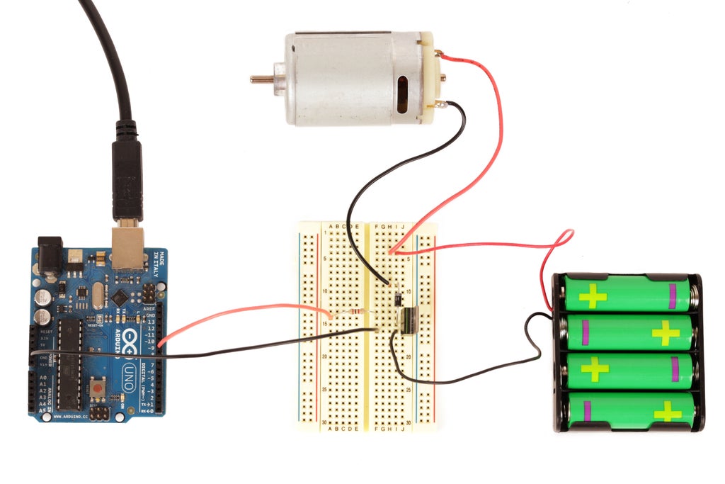
If you want to control the motor's speed, change the wiring to pin 13, and load the fade example to increase and decrease the motor's speed.
It may now have dawned upon you, neither of these solutions will reverse the motor. To make a motor spin backwards, you will need an H-bridge.
Step 16:
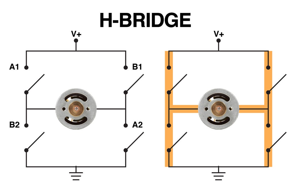
An H-bridge is a circuit that allows a motor's direction to be reversed. More advanced H-bridges - like the kind found inside of servo motors - also allow you to control the speed of the motor.
Essentially, an H-bridge consists of four switches or transistors. In the above example, there is a switch between each pole of the motor and ground. There is also another set of switches between each pole of the motor and power.
When these switches are drawn out in a diagram, they look kind of like an “H”. That is how the circuit gets the name H-bridge.
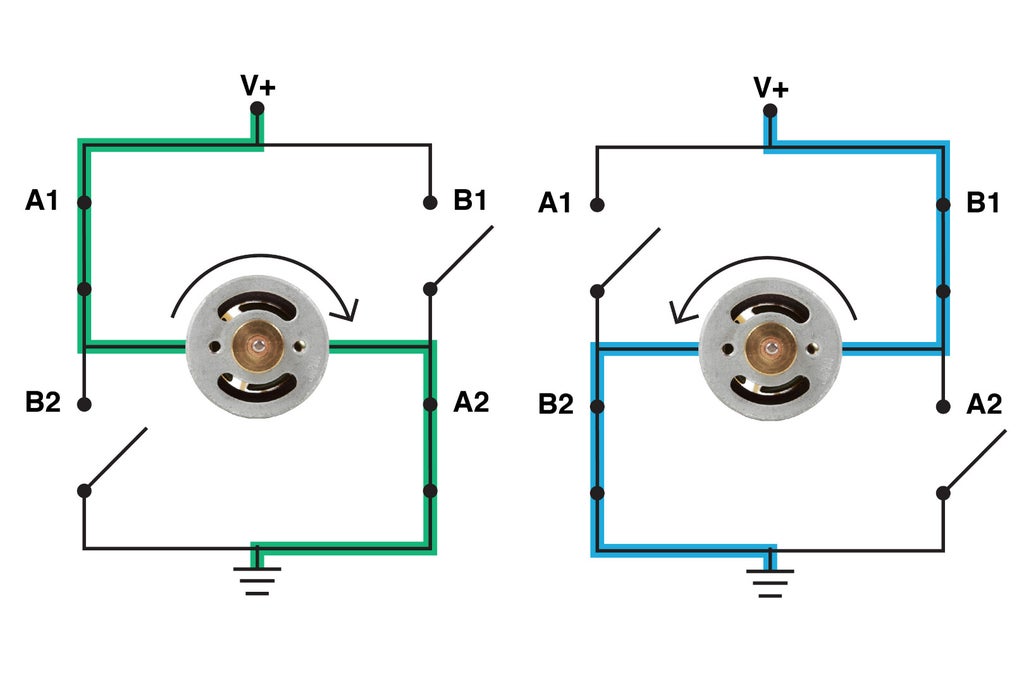
When the set of switches labeled with “A” is closed, power flows through the motor in such a way that it spins clockwise.
When the other “B” set is closed, power flows the opposite direction and the motor spins counterclockwise.
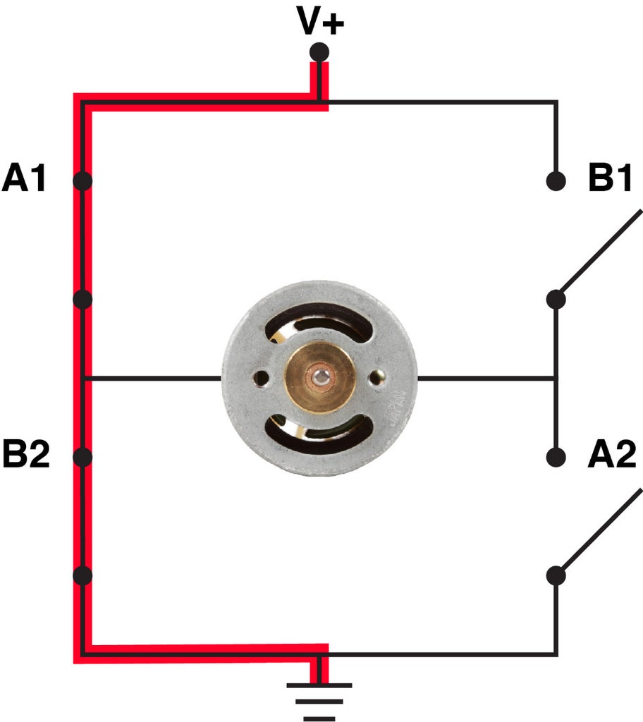
The important thing to remember when dealing with H-bridges is that both sets cannot be closed at the same time, or power and ground will be directly connected, and you will have a short circuit.
As well, if you mix and match the switches such as closing A1 and B2, you will also create a short circuit. It is important that either the “A” switches get closed or the “B” switches. Never both or some combination thereof.
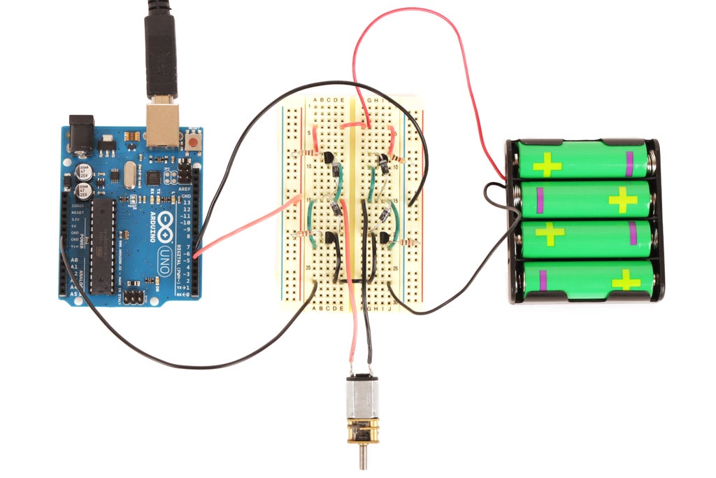
If you want to control speed, you would use four transistors instead of switches and control the base of each transistor using your Arduino.
Above is a crude example of a DIY H-bridge using two PNP (2N3906) and two NPN (2N3904) transistors. Before you go out and build this circuit and put into your project, it is important to keep in mind that these transistors can't handle much current at all. This example should only be tried with a relatively 'very small' motors (no bigger than the one pictured), and is not necessary to build. It is primarily just here to explain the concept of it. We will be using motor controller boards with pre-made H-bridges as we continue through the course.
Now that is out of the way, let's discuss briefly about what is happening. Each side of the "H" consists of a PNP transistor on "top" and a NPN transistor on "bottom." The base of each of these transistors is connected to a common rail through a 1K resistor (to protect the Arduino), and this rail gets connected to an Arduino pin. The emitter of the PNP transistor is connected to power, and the emitter of the NPN transistor is connected to ground. On each side of the 'H', both collectors connect together to join a single motor pin. Also included in the circuit are four 1N4001 silicon protection diodes which are reverse biased between each pin of the motor and the positive voltage supply and ground.
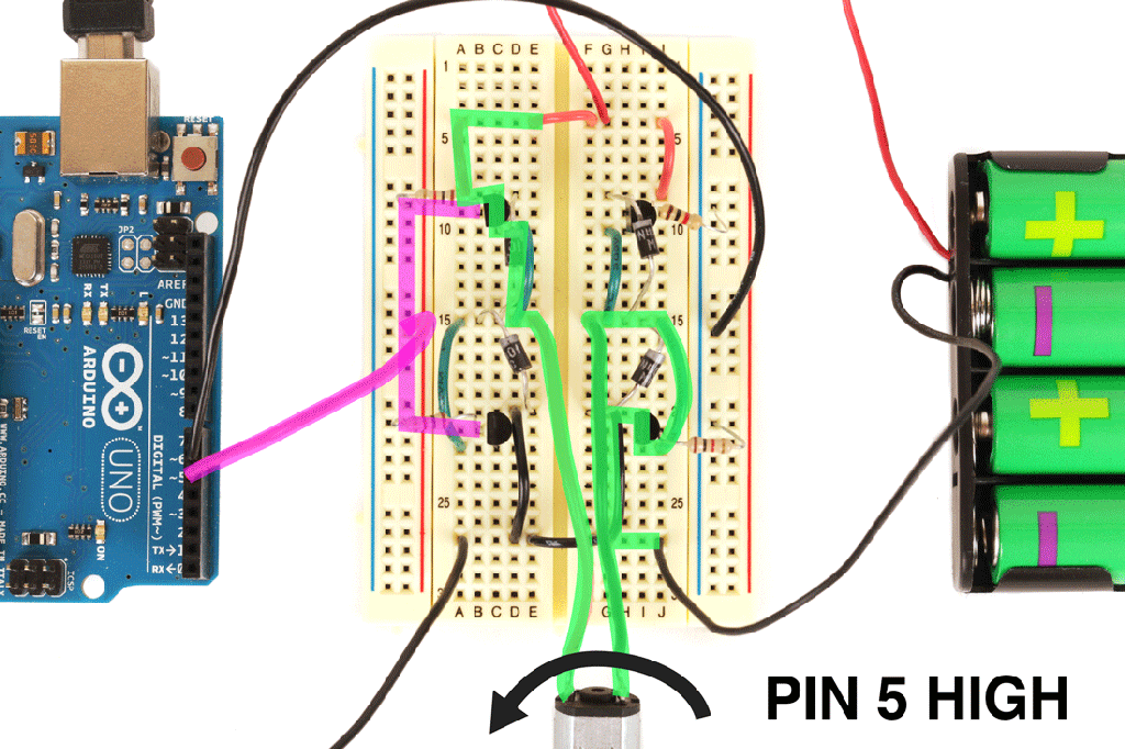
By using a combination of PNP and NPN transistors — as opposed to four NPN transistors — two things are accomplished. First, it creates an arrangement where one transistor on each side is always disengaged, preventing shorts. Secondly, it allows control of the H-bridge with just two digital pins from the Arduino.
For instance, if you have one Arduino pin sending a high signal to one side of the 'H', and the other Arduino pin sending a low signal to the other side, electricity will flow from the PNP on one side to the NPN on the other. If you reverse the Arduino pins, electricity will then flow through the opposite pair of transistors, reversing motor direction.
The motor speed can also be controlled using an H-bridge like this by PWM-ing the positive Arduino pin instead of setting it to HIGH.
If you soldiered ahead and built this circuit, you can use the following code to see it in action:
void setup() {
  // set the digital pins as outputs
  pinMode(5, OUTPUT);
  pinMode(6, OUTPUT);
}

void loop() {
  //spin clockwise
  digitalWrite(5, LOW);
  digitalWrite(6, HIGH);
  delay(2000);

  //spin counterclockwise
  digitalWrite(5, HIGH);
  digitalWrite(6, LOW);
  delay(2000);
}
If you want to test out controlling the speed in both directions, try PWM-ing the base pins of the transistor with this code:
void setup() {
  // set the digital pins as outputs
  pinMode(5, OUTPUT);
  pinMode(6, OUTPUT);
}

void loop() {
  //spin slowly clockwise
  digitalWrite(5, LOW);
  analogWrite(6, 80);
  delay(2000);

  //spin faster counterclockwise
  analogWrite(5, 180);
  digitalWrite(6, LOW);
  delay(2000);
}
Building a very reliable H-bridge is an art form unto itself and outside the scope of this class. Instead, we will be using motor controller shield and modules. These are basically circuit boards with pre-made H-bridges for controlling motors.
Some motors even have their own H-bridge already built in, as you will learn next in the servo lesson.


