

Introduction: Basic Electronics


Getting started with basic electronics is easier than you might think. This Instructable will hopefully demystify the basics of electronics so that anyone with an interest in building circuits can hit the ground running. This is a quick overview into practical electronics and it is not my goal to delve deeply into the science of electrical engineering. If you are interested in learning more about the science of basic electronics, Wikipedia is a good place to start your search.
By the end of this Instructable, anyone with an interest to learn basic electronics should be able to read a schematic and build a circuit using standard electronic components.
For a more comprehensive and hands-on overview of electronics, check out my Electronics Class.
Step 1: Electricity

There are two types of electrical signals , those being alternating current (AC), and direct current (DC).
With alternating current, the direction electricity flows throughout the circuit is constantly reversing. You may even say that it is alternating direction. The rate of reversal is measured in Hertz, which is the number of reversals per second. So, when they say that the US power supply is 60 Hz, what they mean is that it is reversing 120 times per second (twice per cycle).
With Direct Current, electricity flows in one direction between power and ground. In this arrangement there is always a positive source of voltage and ground (0V) source of voltage. You can test this by reading a battery with a multimeter. For great instructions on how to do this, check out Ladyada's multimeter page (you will want to measure voltage in particular).
Speaking of voltage, electricity is typically defined as having a voltage and a current rating. Voltage is obviously rated in Volts and current is rated in Amps. For instance, a brand new 9V battery would have a voltage of 9V and a current of around 500mA (500 milliamps).
Electricity can also be defined in terms of resistance and watts. We will talk a little bit about resistance in the next step, but I am not going to be going over Watts in depth. As you delve deeper into electronics you will encounter components with Watt ratings. It is important to never exceed the Wattage rating of a component, but fortunately that Wattage of your DC power supply can easily be calculated by multiplying the voltage and current of your power source.
If you want a better understanding of these different measurements, what they mean, and how they relate, check out this informative video on Ohm's Law.
Most basic electronic circuits use DC electricity. As such, all further discussion of electricity will revolve around DC electricity.
(Note that some of the links on this page are affiliate links. This does not change the cost of the item for you. I reinvest whatever proceeds I receive into making new projects. If you would like any suggestions for alternative suppliers, please let me know.)
Step 2: Circuits
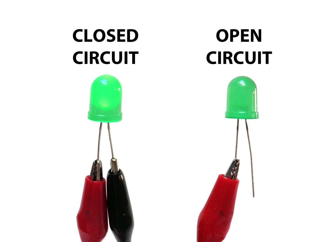
A circuit is a complete and closed path through which electric current can flow. In other words, a closed circuit would allow the flow of electricity between power and ground. An open circuit would break the flow of electricity between power and ground.
Anything that is part of this closed system and that allows electricity to flow between power and ground is considered to be part of the circuit.
Step 3: Resistance

The next very important consideration to keep in mind is that electricity in a circuit must be used.
For instance, in the circuit above, the motor that electricity is flowing through is adding resistance to the flow of electricity. Thus, all of the electricity passing through the circuit is being put to use.
In other words, there needs to be something wired between positive and ground that adds resistance to the flow of electricity and uses it up. If positive voltage is connected directly to ground and does not first pass through something that adds resistance, like a motor, this will result in a short circuit. This means that the positive voltage is connected directly to ground.
Likewise, if electricity passes through a component (or group of components) that does not add enough resistance to the circuit, a short will likewise occur (see Ohm's Law video).
Shorts are bad because they will result in your battery and/or circuit overheating, breaking, catching on fire, and/or exploding.
It is very important to prevent short circuits by making sure that the positive voltage is never wired directly to ground.
That said, always keep in mind that electricity always follows the path of least resistance to ground. What this means is that if you give positive voltage the choice to pass through a motor to ground, or follow a wire straight to ground, it will follow the wire because the wire provides the least resistance. This also means that by using the wire to bypass the source of resistance straight to ground, you have created a short circuit. Always make sure that you never accidentally connect positive voltage to ground while wiring things in parallel.
Also note that a switch does not add any resistance to a circuit and simply adding a switch between power and ground will create a short circuit.
Step 4: Series Vs. Parallel


There are two different ways in which you can wire things together called series and parallel.
When things are wired in series, things are wired one after another, such that electricity has to pass through one thing, then the next thing, then the next, and so on.
In the first example, the motor, switch and battery are all wired in series because the only path for electricity to flow is from one, to the next, and to the next.
When things are wired in parallel, they are wired side by side, such that electricity passes through all of them at the same time, from one common point to another common point
In the next example, the motors are wired in parallel because the electricity passes through both motors from one common point to another common point.
in the final example the motors are wired in parallel, but the pair of parallel motors, switch and batteries are all wired in series. So, the current is split between the motors in a parallel fashion, but still must pass in series from one part of the circuit to the next.
If this does not make sense yet, do not worry. When you start to build your own circuits, all of this will start to become clear.
Step 5: Basic Components

In order to build circuits, you will need to become familiar with a few basic components. These components may seem simple, but are the bread and butter of most electronics projects. Thus, by learning about these few basic parts, you will be able to go a long way.
Bear with me as I elaborate as to what each of these are in the coming steps.
Step 6: Resistors

As the name implies, resistors add resistance to the circuit and reduces the flow of electrical current. It is represented in a circuit diagram as a pointy squiggle with a value next to it.
The different markings on the resistor represent different values of resistance. These values are measured in ohms.
Resistors also come with different wattage ratings. For most low-voltage DC circuits, 1/4 watt resistors should be suitable.
You read the values from left to right towards the (typically) gold band. The first two colors represent the resistor value, the third represents the multiplier, and the fourth (the gold band) represents the tolerance or precision of the component. You can tell the value of each color by looking at a resistor color value chart.
Or... to make your life easier, you could simply look up the values using a graphical resistance calculator.
Anyhow... a resistor with the markings brown, black, orange, gold will translate as follows:
1 (brown) 0 (black) x 1,000 = 10,000 with a tolerance of +/- 5%
Any resistor of over 1000 ohms is typically shorted using the letter K. For instance, 1,000 would be 1K; 3,900, would translate to 3.9K; and 470,000 ohms would become 470K.
Values of ohms over a million are represented using the letter M. In this case, 1,000,000 ohms would become 1M.
Step 7: Capacitors

A capacitor is a component that stores electricity and then discharges it into the circuit when there is a drop in electricity. You can think of it as a water storage tank that releases water when there is a drought to ensure a steady stream.
Capacitors are measured in Farads. The values that you will typically encounter in most capacitors are measured in picofarad (pF), nanofarad (nF), and microfarad (uF). These are often used interchangeably and it helps to have a conversion chart at hand.
The most commonly encountered types of capacitors are ceramic disc capacitors that look like tiny M&Ms with two wires sticking out of them and electrolytic capacitors that look more like small cylindrical tubes with two wires coming out the bottom (or sometimes each end).
Ceramic disc capacitors are non-polarized, meaning that electricity can pass through them no matter how they are inserted in the circuit. They are typically marked with a number code which needs to be decoded. Instructions for reading ceramic capacitors can be found here. This type of capacitor is typically represented in a schematic as two parallel lines.
Electrolytic capacitors are typically polarized. This means that one leg needs to be connected to the ground side of the circuit and the other leg must be connected to power. If it is connected backwards, it won't work correctly. Electrolytic capacitors have the value written on them, typically represented in uF. They also mark the leg which connects to ground with a minus symbol (-). This capacitor is represented in a schematic as a side-by-side straight and curved line. The straight line represents the end which connects to power and the curve connected to ground.
Step 8: Diodes

Diodes are components which are polarized. They only allow electrical current to pass through them in one direction. This is useful in that it can be placed in a circuit to prevent electricity from flowing in the wrong direction.
Another thing to keep in mind is that it requires energy to pass through a diode and this results in a drop of voltage. This is typically a loss of about 0.7V. This is important to keep in mind for later when we talk about a special form of diodes called LEDs.
The ring found on one end of the diode indicates the side of the diode which connects to ground. This is the cathode. It then follows that the other side connects to power. This side is the anode.
The part number of the diode is typically written on it, and you can find out its various electrical properties by looking up its datasheet.
They are represented in schematic as a line with a triangle pointing at it. The line is that side which connected to ground and the bottom of the triangle connects to power.
Step 9: Transistors

A transistor takes in a small electrical current at its base pin and amplifies it such that a much larger current can pass between its collector and emitter pins. The amount of current that passes between these two pins is proportional to the voltage being applied at the base pin.
There are two basic types of transistors, which are NPN and PNP. These transistors have opposite polarity between collector and emitter. For a very comprehensive intro to transistors check out this page.
NPN transistors allow electricity to pass from the collector pin to the emitter pin. They are represented in a schematic with a line for a base, a diagonal line connecting to the base, and a diagonal arrow pointing away from the base.
PNP transistors allow electricity to pass from the emitter pin to the collector pin. They are represented in a schematic with a line for a base, a diagonal line connecting to the base, and a diagonal arrow pointing towards the base.
Transistors have their part number printed on them and you can look up their datasheets online to learn about their pin layouts and their specific properties. Be sure to take note of the transistor's voltage and current rating as well.
Step 10: Integrated Circuits

An integrated circuit is an entire specialized circuit that has been miniaturized and fit onto one small chip with each leg of the chip connecting to a point within the circuit. These miniaturized circuits typically consist of components such as transistors, resistors, and diodes.
For instance, the internal schematic for a 555 timer chip has over 40 components in it.
Like transistors, you can learn all about integrated circuits by looking up their datasheets. On the datasheet you will learn the functionality of each pin. It should also state the voltage and current ratings of both the chip itself and each individual pin.
Integrated circuits come in a variety of different shapes and sizes. As a beginner, you will be mainly working with DIP chips. These have pins for through-hole mounting. As you get more advanced, you may consider SMT chips which are surface mount soldered to one side of a circuit board.
The round notch on one edge of the IC chip indicates the top of the chip. The pin to the top left of the chip is considered pin 1. From pin 1, you read sequentially down the side until you reach the bottom (i.e. pin 1, pin 2, pin 3..). Once at the bottom, you move across to the opposite side of the chip and then start reading the numbers up until you reach the top again.
Keep in mind that some smaller chips have a small dot next to pin 1 instead of a notch at the top of the chip.
There is no standard way that all ICs are incorporated into circuit diagrams, but they are often represented as boxes with numbers in them (the numbers representing the pin number).
Step 11: Potentiometers

Potentiometers are variable resistors. In plain English, they have some sort of knob or slider that you turn or push to change resistance in a circuit. If you have ever used a volume knob on a stereo or a sliding light dimmer, then you have used a potentiometer.
Potentiometers are measured in ohms like resistors, but rather than having color bands, they have their value rating written directly on them (i.e. "1M"). They are also marked with an "A" or a "B, " which indicated the type of response curve it has.
Potentiometers marked with a "B" have a linear response curve. This means that as you turn the knob, the resistance increases evenly (10, 20, 30, 40, 50, etc.). The potentiometers marked with an "A" have a logarithmic response curve. This means that as you turn the knob, the numbers increase logarithmically (1, 10, 100, 10,000 etc.)
Potentiometers have three legs as to create a voltage divider, which is basically two resistors in series. When two resistors are put in series, the point between them is a voltage that is a value somewhere between the source value and ground.
For instance, if you have two 10K resistors in series between power (5V) and ground (0V), the point where these two resistors meet will be half the power supply (2.5V) because both of the resistors have identical values. Assuming this middle point is actually the center pin of a potentiometer, as you turn the knob, the voltage on the middle pin will actually increase towards 5V or decrease toward 0V (depending which direction that you turn it). This is useful for adjusting the intensity of an electrical signal within a circuit (hence its use as a volume knob).
This is represented in a circuit as a resistor with an arrow pointing towards the middle of it.
If you only connect one of the outer pins and the center pin to the circuit, you are only changing the resistance within the circuit and not the voltage level on the middle pin. This too is a useful tool for circuit building because often you just want to change the resistance at a particular point and not create an adjustable voltage divider.
This configuration is often represented in a circuit as a resistor with an arrow coming out of one side and looping back in to point towards the middle.
Step 12: LEDs

LED stands for light emitting diode. It is basically a special type of diode that lights up when electricity passes through it. Like all diodes, the LED is polarized and electricity is only intended to pass through in one direction.
There are typically two indicators to let you know what direction electricity will pass through and LED. The first indicator that the LED will have a longer positive lead (anode) and a shorter ground lead (cathode). The other indicator is a flat notch on the side of the LED to indicate the positive (anode) lead. Keep in mind that not all LEDs have this indication notch (or that it is sometimes wrong).
Like all diodes, LEDs create a voltage drop in the circuit, but typically do not add much resistance. In order to prevent the circuit from shorting, you need to add a resistor in series. To figure out how large of a resistor you need for optimum intensity, you can use this online LED calculator to figure out how much resistance is needed for a single LED. It is often good practice to use a resistor that is slightly larger in the value than what is returned by calculator.
You may be tempted to wire LEDs in series, but keep in mind that each consecutive LED will result in a voltage drop until finally there is not enough power left to keep them lit. As such, it is ideal to light up multiple LEDs by wiring them in parallel. However, you need to make certain that all of the LEDs have the same power rating before you do this (different colors often are rated differently).
LEDs will show up in a schematic as a diode symbol with lightning bolts coming off of it, to indicate that it is a glowing diode.
Step 13: Switches

A switch is basically a mechanical device that creates a break in a circuit. When you activate the switch, it opens or closes the circuit. This is dependent on the type of switch it is.
Normally open (N.O.) switches close the circuit when activated.
Normally closed (N.C.) switches open the circuit when activated.
As switches get more complex they can both open one connection and close another when activated. This type of switch is a single-pole double-throw switch (SPDT).
If you were to combine two SPDT switches into one single switch, it would be called a double-pole double-throw switch (DPDT). This would break two separate circuits and open two other circuits, every time the switch was activated.
Step 14: Batteries

A battery is a container which converts chemical energy into electricity. To over-simplify the matter, you can say that it "stores power."
By placing batteries in series you are adding the voltage of each consecutive battery, but the current stays the same. For instance, a AA-battery is 1.5V. If you put 3 in series, it would add up to 4.5V. If you were to add a fourth in series, it would then become 6V.
By placing batteries in parallel the voltage remains the same, but the amount of current available doubles. This is done much less frequently than placing batteries in series, and is usually only necessary when the circuit requires more current than a single series of batteries can offer.
It is recommend that you get a range of AA battery holders. For instance, I would get an assortment that holds 1, 2, 3, 4, and 8 AA batteries.
Batteries are represented in a circuit by a series of alternating lines of different length. There are also additional marking for power, ground and the voltage rating.
Step 15: Breadboards

Breadboards are special boards for prototyping electronics. They are covered with a grid of holes, which are split into electrically continuous rows.
In the central part there are two columns of rows that are side-by-side. This is designed to allow you to be able to insert an integrated circuit into the center. After it is inserted, each pin of the integrated circuit will have a row of electrically continuous holes connected to it.
In this way, you can quickly build a circuit without having to do any soldering or twisting wires together. Simply connect the parts that are wired together into one of the electrically continuous rows.
On each edge of the breadboard, there typically runs two continuous bus lines. One is intended as a power bus and the other is intended as a ground bus. By plugging power and ground respectively into each of these, you can easily access them from anywhere on the breadboard.
Step 16: Wire

In order to connect things together using a breadboard, you either need to use a component or a wire.
Wires are nice because they allow you to connect things without adding virtually no resistance to the circuit. This allows you to be flexible as to where you place parts because you can connect them together later with wire. It also allows you to connect a part to multiple other parts.
It is recommended that you use insulated 22awg (22 gauge) solid core wire for breadboards. You used to be able to find it at Radioshack, but instead could use the hookup wire linked to above. Red wire typically indicates a power connection and black wire represents a ground connection.
To use wire in your circuit, simply cut a piece to size, strip a 1/4" of insulation from each end of the wire and use it to connect points together on the breadboard.
Step 17: Your First Circuit
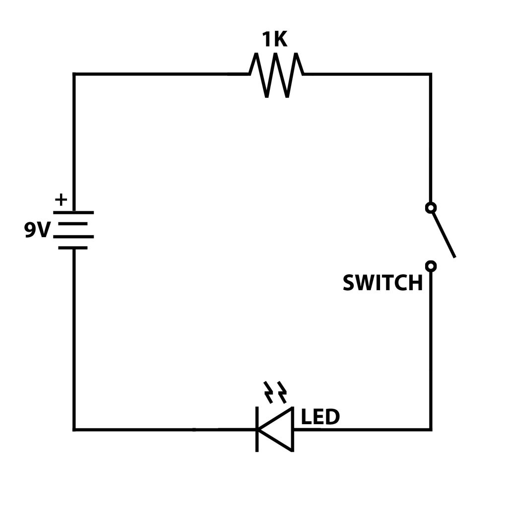
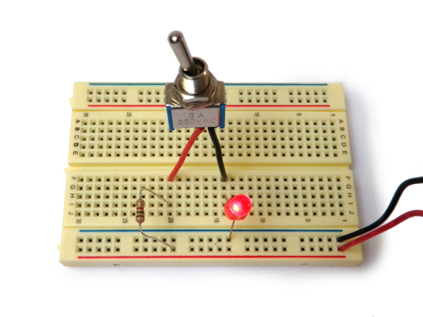
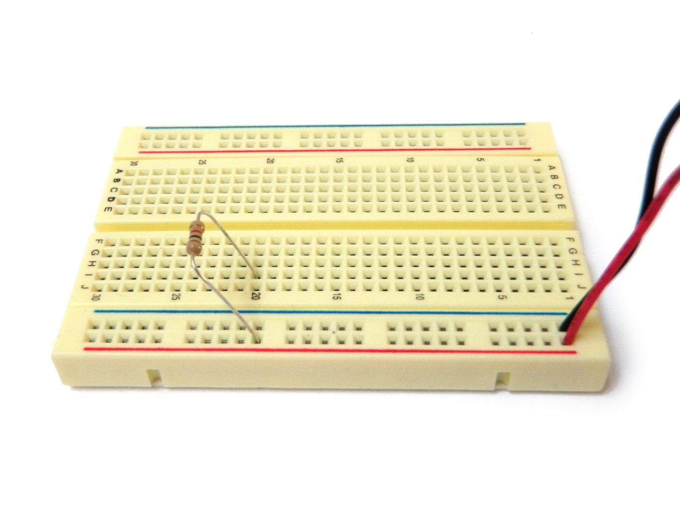
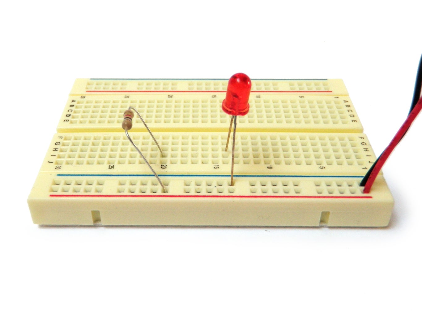

Parts List:
1K ohm - 1/4 Watt resistor
5mm red LED
SPST toggle switch
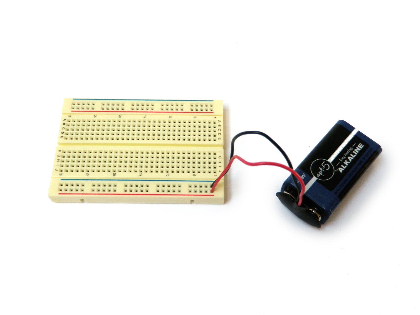
9V battery connector
If you look at the schematic you will see that the 1K resistor, LED, and switch are all connected in series with the 9V battery. When you build the circuit, you will be able to turn the LED on and off with the switch.
You can look up the color code for a 1K resistor using the graphical resistance calculator. Also, remember that the LED needs to be plugged in the right way (hint - the long leg goes to the positive side of the circuit).
I needed to solder a solid core wire to each leg of the switch. For instructions on how to do that, check out the "How to Solder" Instructable. If this is too much of a pain for you to do, simply leave the switch out of the circuit.
If you decide to use the switch, open and close it to see what happens when you make and break the circuit.
Step 18: Your Second Circuit

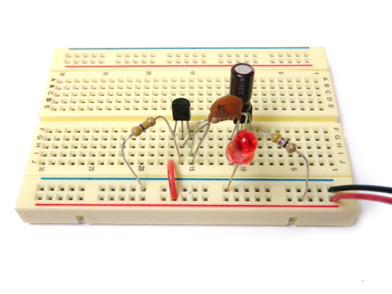


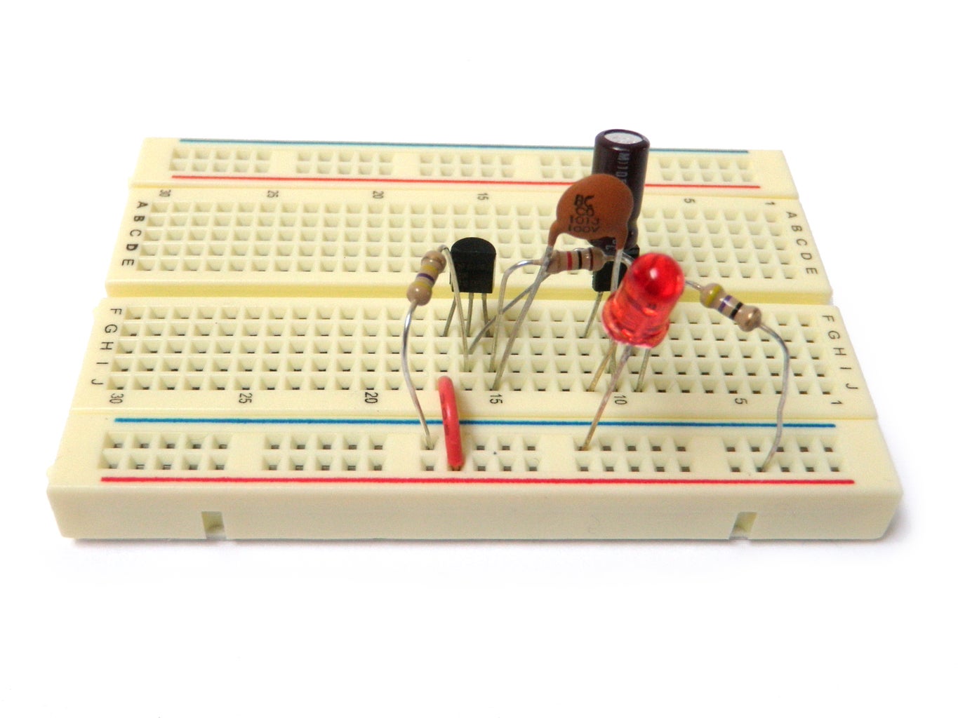


Parts List:
2N3904 PNP transistor
2N3906 NPN transistor
47 ohm - 1/4 Watt resistor
1K ohm - 1/4 Watt resistor
470K ohm - 1/4 Watt resistor
10uF electrolytic capacitor
0.01uF ceramic disc capacitor
5mm red LED
3V AA battery holder
Optional:
10K ohm - 1/4 Watt resistor
1M potentiometer
This next schematic may look daunting, but it is actually rather straight-forward. It is using all of the parts that we have just gone over to automatically blink an LED.
Any general purpose NPN or PNP transistors should do for the circuit, but should you want to follow along at home, I am using 293904 (NPN) and 2N3906 (PNP) transistors. I learned their pin layouts by looking up their datasheets. A good source for quickly finding datasheets is Octopart.com. Simply search for the part number and you should find a picture of the part and link to the datasheet.
For instance, from the datasheet for the 2N3904 transistor, I was quickly able to see that pin 1 was the emitter, pin 2 was the base, and pin 3 was the collector.
Aside from the transistors, all of the resistors, capacitors, and LED should be straight-forward to connect. However, there is one tricky bit in the schematic. Notice the half-arch near the transistor. This arch indicates that the capacitor jumps over the trace from the battery and connects to the base of the PNP transistor instead.
Also, when building the circuit, don't forget to keep in mind that the electrolytic capacitors and LED are polarized and will only work in one direction.
After you finish building the circuit and plug in the power, it should blink. If it does not blink, carefully check all of your connections and orientation of all of the parts.
A trick for quickly debugging the circuit is counting components in the schematic versus components on your breadboard. If they don't match, you left something out. You can also do the same counting trick for the number of things that connect to a particular point in the circuit.
Once it is working, try changing the value of 470K resistor. Notice that by increasing the value of this resistor, the LED blinks slower and that by decreasing it, the LED blinks faster.
The reason for this is that the resistor is controlling the rate at which the 10uF capacitor is filling and discharging. This is directly related to the blinking of the LED.
Replace this resistor with a 1M potentiometer that is in series with a 10K resistor. Wire it such that one side of the resistor connects to an outer pin on the potentiometer and the other side connects to the base of the PNP transistor. The center pin of the potentiometer should connect to ground. The rate of blinking now changes when you turn the knob and sweep through the resistance.
Step 19: Your Third Circuit


Parts List:
555 Timer IC
1K ohm - 1/4 Watt resistor
10K ohm - 1/4 Watt resistor
1M ohm - 1/4 Watt resistor
10uF electrolytic capacitor
0.01uF ceramic disc capacitor
Small Speaker
9V battery connector
This last circuit is using a 555 timer chip to make noise using a speaker.
What is happening is that the configuration of components and connections on the 555 chip is causing pin 3 to oscillate rapidly between high and low. If you were to graph these oscillations, it would look like a square wave (a wave the alternates between two power levels). This wave then rapidly pulses the speaker, which displaces air at such a high frequency that we hear this as a steady tone of that frequency.
Make sure that the 555 chip is straddling the center of the breadboard, such that none of the pins might get accidentally connected. Aside from that, simply make the connections as specified in the schematic diagram.
Also note the "NC" symbol on the schematic. This stands in for "No Connect," which obviously means nothing connects to that pin in this circuit.
You can read all about 555 chips on this page and see a great selection of additional 555 schematics on this page.
In terms of the speaker, use a small speaker like you might find inside of a musical greeting card. This configuration can't drive a large speaker, the smaller the speaker you can find, the better off that you will be. Most speakers are polarized, so make certain that you have the negative side of the speaker connected to ground (if it requires it).
If you want to take it a step farther, you can create a volume knob by connecting one outer pin of a 100K potentiometer to pin 3, the middle pin to the speaker, and the the remaining outer pin to ground.
Step 20: You're on Your Own

Okay... You are not exactly on your own. The internet is full of people who know how to do this stuff and have documented their work such that you can learn how to do it as well. Go forth and seek out what you want to make. If the circuit does not yet exist, chances are there is documentation of something similar already online.
A great place to start finding circuit schematic is the Discover Circuits site. They have a comprehensive list of fun circuits to experiment with.
If you have any additional advice about basic electronics for beginners, please share it in the comments below.

Did you find this useful, fun, or entertaining?
Follow @madeineuphoria to see my latest projects.

Participated in the
The Teacher Contest

Participated in the
ShopBot Challenge

Participated in the
The Mad Science Fair


