Introduction: SOLAR WIRELESS LAMP WITH MAGNETIC FLEXIBLE ARM

About: PLC, Arduino - Do it yourself project

This project was made from a broken lamp & nodeMCU. This decorative lamp can be adjusted in any directions & attached on magnetic materials or put on the table. It can be controlled in two modes as follows:

- Wireless control mode, as YouTube link below:

- Interactive control mode, as YouTube link below:

Step 1: BILL OF MATERIALS

B.O.M list:

For interactive mode, I use MPU6050 to get gyro data from NodeMCU to control lamp's color.

Materials picture for this project:

Step 2: CIRCUIT

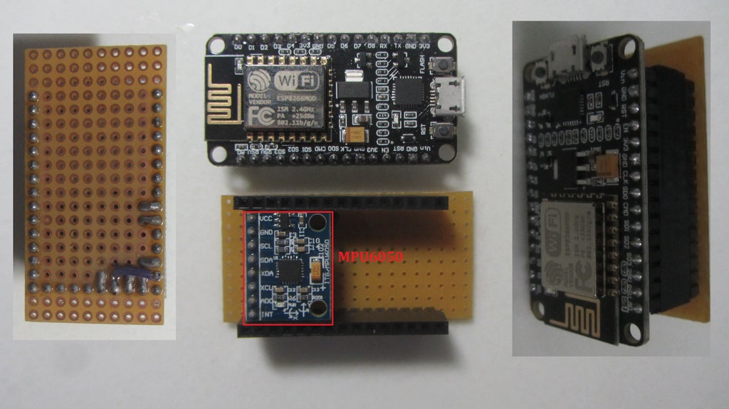
This is very simple circuit, as Fritzing schematic above, with 1 RGB Led common anode type, three limit current resistors R100 & MPU6050.

The reflector is used from any broken lamps & connected to nodeMCU base by 2 bolts or stick them with strong glue.

Installation work:
Schematic below:

Step 3: MAGNETIC BASE - FLEXIBLE ARM

Flexible arm can be reused from broken flexible water taps. Something like that:

With some tips, we try to connect them to the permanent magnet base at bottom of flexible arm. On top, we made a drill hole for connecting to our circuit board and solar/battery charger.With this base, we can put lamp on surface like table, floors….; or it can be attached on magnetic materials like steel pillar, steel structure.

Step 4: SOLAR – BATTERY CHARGER

It came from a damaged charging lamp. I added an on/off switch and power wires supply to nodeMCU. It also has one USB port outlet and one plug for battery charger.

Step 5: CONNECT ALL TOGETHER

Connecting all parts: NodeMCU & reflector, solar & battery cells, flexible arm together.

FINISH

CHARGING MODE

Step 6: INTERACTIVE CONTROL PROGRAM

Color will be changed when we adjust flexible arm or rotate the lamp.

INTERACTIVE LAMP

#include
// MPU6050 Slave Device Address
const uint8_t MPU6050SlaveAddress = 0x68;
// Select SDA and SCL pins for I2C communication - Pin default in WIRE LIBRARY: SCL - D1 & SDA - D2 on NODEMCU
// const uint8_t SCL = D1;
// const uint8_t SDA = D2;
const int R = 14;
const int G = 12;
const int B = 13;
// MPU6050 few configuration register addresses
const uint8_t MPU6050_REGISTER_SMPLRT_DIV = 0x19;
const uint8_t MPU6050_REGISTER_USER_CTRL = 0x6A;
const uint8_t MPU6050_REGISTER_PWR_MGMT_1 = 0x6B;
const uint8_t MPU6050_REGISTER_PWR_MGMT_2 = 0x6C;
const uint8_t MPU6050_REGISTER_CONFIG = 0x1A;
const uint8_t MPU6050_REGISTER_GYRO_CONFIG = 0x1B;
const uint8_t MPU6050_REGISTER_ACCEL_CONFIG = 0x1C;
const uint8_t MPU6050_REGISTER_FIFO_EN = 0x23;
const uint8_t MPU6050_REGISTER_INT_ENABLE = 0x38;
const uint8_t MPU6050_REGISTER_ACCEL_XOUT_H = 0x3B;
const uint8_t MPU6050_REGISTER_SIGNAL_PATH_RESET = 0x68;
int16_t AccelX, AccelY, AccelZ, Temperature, GyroX, GyroY, GyroZ;
void setup() {
pinMode(R, OUTPUT);
pinMode(G, OUTPUT);
pinMode(B, OUTPUT);
//Serial.begin(9600);
Wire.begin(SDA, SCL);
MPU6050_Init();
}
void loop() {
uint16_t Ax, Ay, Az, T, Gx, Gy, Gz;
uint16_t Red, Green, Blue;
Read_RawValue(MPU6050SlaveAddress, MPU6050_REGISTER_ACCEL_XOUT_H);
// Take absolute value
Ax = myAbs(AccelX);
Ay = myAbs(AccelY);
Az = myAbs(AccelZ);
// Scale in range
Red = map(Ax,0,16384,0,1023);
Green = map(Ay,0,16384,0,1023);
Blue = map(Az,0,16384,0,1023);
// Serial print to check
//Serial.print("Red: "); Serial.print(Red);
//Serial.print("Green: "); Serial.print(Green);
//Serial.print("Blue: "); Serial.print(Blue);
// Write analog to LED
analogWrite(R, Red); // R
analogWrite(G, Green); // G
analogWrite(B, Blue); // B
delay(200);
}
void I2C_Write(uint8_t deviceAddress, uint8_t regAddress, uint8_t data){
Wire.beginTransmission(deviceAddress);
Wire.write(regAddress);
Wire.write(data);
Wire.endTransmission();
}
// Read all 14 registers
void Read_RawValue(uint8_t deviceAddress, uint8_t regAddress){
Wire.beginTransmission(deviceAddress);
Wire.write(regAddress);
Wire.endTransmission();
Wire.requestFrom(deviceAddress, (uint8_t)14);
AccelX = (((int16_t)Wire.read()<<8) | Wire.read());
AccelY = (((int16_t)Wire.read()<<8) | Wire.read());
AccelZ = (((int16_t)Wire.read()<<8) | Wire.read());
Temperature = (((int16_t)Wire.read()<<8) | Wire.read());
GyroX = (((int16_t)Wire.read()<<8) | Wire.read());
GyroY = (((int16_t)Wire.read()<<8) | Wire.read());
GyroZ = (((int16_t)Wire.read()<<8) | Wire.read());
}
// Configure MPU6050
void MPU6050_Init(){
delay(150);
I2C_Write(MPU6050SlaveAddress, MPU6050_REGISTER_SMPLRT_DIV, 0x07);
I2C_Write(MPU6050SlaveAddress, MPU6050_REGISTER_PWR_MGMT_1, 0x01);
I2C_Write(MPU6050SlaveAddress, MPU6050_REGISTER_PWR_MGMT_2, 0x00);
I2C_Write(MPU6050SlaveAddress, MPU6050_REGISTER_CONFIG, 0x00);
I2C_Write(MPU6050SlaveAddress, MPU6050_REGISTER_GYRO_CONFIG, 0x00);//set +/-250 degree/second full scale
I2C_Write(MPU6050SlaveAddress, MPU6050_REGISTER_ACCEL_CONFIG, 0x00);// set +/- 2g full scale
I2C_Write(MPU6050SlaveAddress, MPU6050_REGISTER_FIFO_EN, 0x00);
I2C_Write(MPU6050SlaveAddress, MPU6050_REGISTER_INT_ENABLE, 0x01);
I2C_Write(MPU6050SlaveAddress, MPU6050_REGISTER_SIGNAL_PATH_RESET, 0x00);
I2C_Write(MPU6050SlaveAddress, MPU6050_REGISTER_USER_CTRL, 0x00);
}
// Absolute Value
float myAbs(float in){
return (in)>0?(in):-(in);
}

Step 7: WIRELESS CONTROL PROGRAM AND ANDROID APPLICATION

Another way, we can use Android App to control RGB LED with Android in WiFi Network. Link Android App:
NODEMCU control RGB LED APP

For Arduino program, you can refer to:

http://microcontrollerkits.blogspot.com/2016/05/es...

After uploading program to NodeMCU, the first run will give us the NodeMCU's IP address on serial print. In my case, it is: 192.164.1.39 at port 80.

Now, we can control wireless lamp with laptop/ tablet/mobile phone by entering address above into internet explorer.

Or using Android app:

Step 8: SOME PICTURES

Trash to Treasure

Participated in the
Trash to Treasure

Microcontroller Contest

Participated in the
Microcontroller Contest