

Introduction: Task 5.1 HD


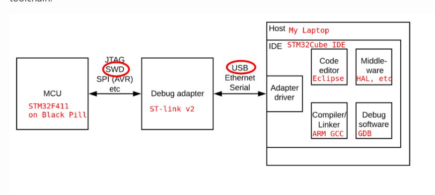
In this tutorial, we'll dive into the world of STM32 microcontrollers using STM32 Black Pill board and STM32CubeIDE. We'll learn how to set up the development environment, configure GPIO pins, and implement a sequence where three LEDs blink in various combinations. These combinations will include patterns such as 100, 010, 001, 110, and others, totaling nine distinct combinations using HAL (Hardware Abstraction Layer) programming.
Attachments
Supplies
- STM32 Black Pill board
- USB cable
- Computer with STM32CubeIDE installed
- Three LEDs
- Resistors (220-470 ohms)
- Breadboard and jumper wires
Step 1: Setting Up STM32CubeIDE
- Firstly Download and install STM32CubeIDE from the official STMicroelectronics website.
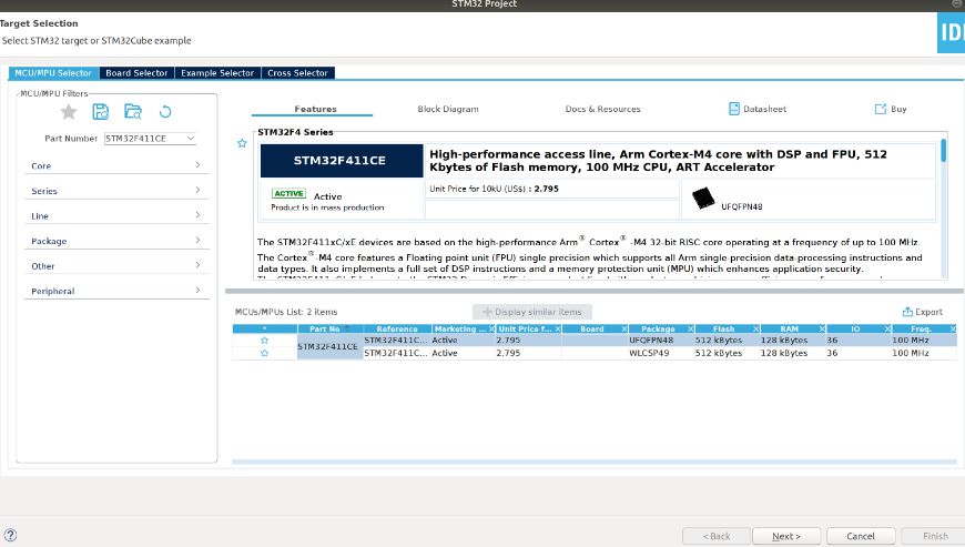
- Launch STM32CubeIDE and create a new STM32 project for your Black Pill board.
Attachments
Step 2: Configuring GPIO Pins

- Open the Pinout & Configuration tab in STM32CubeIDE.
- Configure three GPIO pins to control the LEDs. For example, you can use GPIO pins PA0, PA1, and PA2.
- Make sure to set the pins as Output Push-Pull in the GPIO configuration.
Step 3: Writing the Code
- In STM32CubeIDE, navigate to the Core folder and open the main.c file.
- Initialize the HAL library by adding #include "stm32f401C_hal.h" at the beginning of the file.
- After that we will write the code to blink the LEDs in various combinations.
Attachments

Step 4: Compiling and Flashing the Code
- Click on the hammer icon in STM32CubeIDE.
- Connect STM32 Black Pill board to y computer via USB.
- Click on the play button to flash the code onto the board.
Attachments

Step 5: Testing
- Once the code is successfully runs, we see the LEDs blinking in various combinations .
Step 6: Conclusion
we created a project using STM32 Black Pill and STM32CubeIDE to implement LED blinking sequences. This project serves as a great starting point for learning embedded systems development with STM32 microcontrollers.


![Tim's Mechanical Spider Leg [LU9685-20CU]](https://content.instructables.com/FFB/5R4I/LVKZ6G6R/FFB5R4ILVKZ6G6R.png?auto=webp&crop=1.2%3A1&frame=1&width=306)


