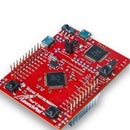
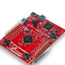
Introduction: Tiva C Projects: Control Blinking RGB LED by Switch
How to control blinking RGB LED by switch
In this instructable, we will combine this instructable with this one.
Step 1: Watch the Video
Step 2: How to Use GPIO Pins
To use GPIO pin as an output pin, look at this instructable
To use GPIO pin as an input pin, look at this instructable
Step 3: Let`s Write a Code
#define SYSCTL_RCGCGPIO_R (*((volatile int *) 0x400FE608))
#define GPIO_PORTF_DIR_R (*((volatile int *) 0x40025400))
#define GPIO_PORTF_DEN_R (*((volatile int *) 0x4002551C))
#define GPIO_PORTF_DATA_R (*((volatile int *) 0x4002507C))
#define GPIO_PORTF_PUR_R (*((volatile int *) 0x40025510))
#define GPIO_PORTF_LOCK_R (*((volatile int *) 0x40025520))
#define GPIO_PORTF_CR_R (*((volatile int *) 0x40025524))
#define GPIO_PORTF_CLK_EN 0x20 //clock enable of PORTF
#define GPIO_PORTF_PIN0_EN 0x01 //Enable SW2
#define GPIO_PORTF_PIN1_EN 0x02 //Enable RED LED
#define GPIO_PORTF_PIN2_EN 0x04 //Enable BLUE LED
#define GPIO_PORTF_PIN3_EN 0x08 //Enable GREEN LED
#define GPIO_PORTF_PIN4_EN 0x10 //Enable SW1
void PORTF_Init(void);
void Delay(unsigned int);
int main(void)
{
unsigned char flag = 0;
unsigned int SW1,SW2;
PORTF_Init();
while(1)
{
SW1 = GPIO_PORTF_DATA_R & 0x10;
SW2 = GPIO_PORTF_DATA_R & 0x01;
if(!SW1 && SW2) //if SW1 is pressed and SW2 is not
{
flag = 1;
}
else if(SW1 &&!SW2) //if SW2 is pressed and SW1 is not
{
flag = 2;
}
if(flag == 1)
{
GPIO_PORTF_DATA_R = 0x02; //Turn on RED LED
Delay(50); //Delay 50 msec
GPIO_PORTF_DATA_R = 0x04; //Turn on BLUE LED
Delay(50); //Delay 50 msec
GPIO_PORTF_DATA_R = 0x08; //Turn on GREEN LED
Delay(50); //Delay 50 msec
}
else
{
GPIO_PORTF_DATA_R = 0x00; //Turn off RGB LED
}
}
}
//Delay Function (pass number in msec)
void Delay(unsigned int counter)
{
volatile unsigned int i; //volatile keyword is very important for blinking LED correctly
counter *= 4000;
for(i=0;i<counter;i++);
}
void PORTF_Init(void)
{
SYSCTL_RCGCGPIO_R |= GPIO_PORTF_CLK_EN; //enable clock of PORTF
GPIO_PORTF_LOCK_R = 0x4C4F434B; //unlock GPIO of PORTF
GPIO_PORTF_CR_R = 0x01; //Enable GPIOPUR register enable to commit
GPIO_PORTF_PUR_R |= GPIO_PORTF_PIN0_EN + GPIO_PORTF_PIN4_EN; //Enable Pull Up SW1,SW2 GPIO_PORTF_DIR_R |= GPIO_PORTF_PIN1_EN + GPIO_PORTF_PIN2_EN + GPIO_PORTF_PIN3_EN; //Make PF1,PF2,PF3 as output and PF4 as input by default
GPIO_PORTF_DEN_R |= GPIO_PORTF_PIN0_EN + GPIO_PORTF_PIN1_EN + GPIO_PORTF_PIN2_EN+ GPIO_PORTF_PIN3_EN + GPIO_PORTF_PIN4_EN; //enable PF1,PF2,PF3,PF4 pins as digital GPIO
}


