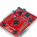
Introduction: Tiva C Projects: Control Built-in LED by PUSH BUTTON on Tiva C
How to control built-in LED by push button.
hold on the push button to turn on the red LED and release the push button to turn off it.
Let`s do it
Step 1: Watch the Video
Step 2: How to Use GPIO Pin As Input Pin
In previous Instructables, we used GPIO pins as output pins
In this instructable, we will use GPIO pin as input pin.
To use GPIO pin as input pin, you should do the following:
- unlock GPIO for PORTF by GPIO LOCK register and writing 0x4C4F434B to it
#define GPIO_PORTF_LOCK_R (*((volatile int *) 0x40025520))
base address of PORTF = 0x40025000
offset of LOCK register = 0x520
so 0x40025000 + 0x520 = 0x40025520
GPIO_PORTF_LOCK_R = 0x4C4F434B //unlocks the GPIOCR register
- enable GPIO Commit (GPIOCR) register to enable GPIOPUR register
#define GPIO_PORTF_CR_R (*((volatile int *) 0x40025524))
base address of PORTF = 0x40025000
offset of LOCK register = 0x524
so 0x40025000 + 0x520 = 0x40025524
set 0x01 to its value to enable GPIOPUR register
- enable Pull up register by GPIOPUR register
#define GPIO_PORTF_PUR_R (*((volatile int *) 0x40025510))
base address of PORTF = 0x40025000
offset of LOCK register = 0x510
so 0x40025000 + 0x520 = 0x40025510
set 1 to the corresponding pin you want to use. In this instructable, we use PF4 so let pin 5 of GPIOPUR register as high
GPIO_PORTF_PUR_R |= 0x10
- let the corresponding pin in GPIODIR as low to use it as input pin
but by default, all pins are cleared so you can use it as input pin without let the corresponding pin low.
- Checking if the user pressed on the switch or not
if(GPIO_PORTF_DATA_R & 0x10) --> true if user does not press on the switch (pull up resistor) and false if user pressed on the switch
0x10 --> can be changed according to the used pin (there we use PF4 so we used 0001000)
if we want to use PF0 (we will use 0x01 instead of 0x10)
Step 3: Let`s Write the Code
#define SYSCTL_RCGCGPIO_R (*((volatile int *) 0x400FE608))
#define GPIO_PORTF_DIR_R (*((volatile int *) 0x40025400))
#define GPIO_PORTF_DEN_R (*((volatile int *) 0x4002551C))
#define GPIO_PORTF_DATA_R (*((volatile int *) 0x4002507C))
#define GPIO_PORTF_PUR_R (*((volatile int *) 0x40025510))
#define GPIO_PORTF_LOCK_R (*((volatile int *) 0x40025520))
#define GPIO_PORTF_CR_R (*((volatile int *) 0x40025524))
#define GPIO_PORTF_CLK_EN 0x20 //clock enable of PORTF
#define GPIO_PORTF_PIN1_EN 0x02 //Enable RED LED
#define GPIO_PORTF_PIN4_EN 0x10 //Enable SW1
int main(void)
{
SYSCTL_RCGCGPIO_R |= GPIO_PORTF_CLK_EN; //enable clock of PORTF
GPIO_PORTF_LOCK_R = 0x4C4F434B; //unlock GPIO of PORTF
GPIO_PORTF_CR_R = 0x01; //Enable GPIOPUR register enable to commit
GPIO_PORTF_PUR_R |= GPIO_PORTF_PIN4_EN; //Enable Pull Up SW1
GPIO_PORTF_DIR_R |= GPIO_PORTF_PIN1_EN; //Make PF1 as output and PF4 as input by default GPIO_PORTF_DEN_R |= GPIO_PORTF_PIN1_EN + GPIO_PORTF_PIN4_EN; //enable PF1 and PF4 pins as digital GPIO
while(1)
{
if(GPIO_PORTF_DATA_R & 0x10)
{
GPIO_PORTF_DATA_R = 0x00; //turn off RED LED
}
else
{
GPIO_PORTF_DATA_R = GPIO_PORTF_PIN1_EN; //turn on RED LED
}
}
}


![Tim's Mechanical Spider Leg [LU9685-20CU]](https://content.instructables.com/FFB/5R4I/LVKZ6G6R/FFB5R4ILVKZ6G6R.png?auto=webp&crop=1.2%3A1&frame=1&width=306)


