

Introduction: Transparent OLED Test Board With XIAO


Greetings everyone and welcome to the future.
This is a transparent OLED display that works as a regular SSD1306-like display, but we can see through it, and this is actually pretty amazing.
This display had one significant flaw: it was fragile and challenging to use while keeping it secure during testing and prototyping.
I created this straightforward test board/bench to retain this display in one piece. It consists of a custom PCB connecting an XIAO M0 board with the converter board of this screen and also holds a 3D-printed screen holder.
This instructables will explain how this project was created and how you can create it in a few simple steps, so let's get started.
Supplies
Materials Required
Following were the materials used in this built-
- XIAO M0 DEV Board
- Custom PCBs (Provided by Seeed Studio)
- Fermion 1.5-inch 128x64 OLED Transparent Display
- Female Header pins
- 3D Parts
- M2 Screws
- M3 Bolts
- M3 Threaded inserts
- Soldering Iron
Step 1: 1.51” SSD1309 Transparent Monochrome OLED Display

Here's something really cool: a convector module-based Transparent monochrome OLED display based on the SSD1309. The compact converter has two available connections for convenience: GDI and SPI.
This Display adopts SPI communication with an onboard GDI interface, which greatly reduces the wiring complexity as there's just one Flex PCB that is connected to the converter module.
Below are its specifications
- Screen Interface: 8-bit 68xx/80xx Parallel, 3-/4-wire SPI, 12C
- Adapter Interface: SPI, GDI
- Adapter Size: 18 x 28mm/0.71 x 1.10inch
- Working Voltage: 3.3V
- View Angle: full view
- Driver Chip: SSD1309
- Display Color: blue
- Display Area: 35.05 x 15.32 (mm)/1.40 x 0.60inch
- Pixel Pitch: 0.274 x 0.274mm
- Pixel Size: 0.254 x 0.254mm
- Screen Size: 41.92x27.08mm/1.65 x 1.07inch
- The fully transparent region resolution :128*56
- Working Temperature: -40~70 ℃
This Display has a Wiki Page that is well documented; if you need more in-depth information about this play, check out its wiki page.
Step 2: TEST BOARD


The idea behind this is straightforward: Transparent OLEDs do not come with screen protectors or holders, which are essential during prototyping. We can either add them to a breadboard and take extra care around them, or we can create a test bench or board with a screen holder and a specific MCU for controlling the display, as I did in this project.
In order to construct the converter module with an OLED display, we first model everything in Fusion360 and create a PCB on which to mount the XIAO M0 board.
Next, we create a screen holder modeled after the screen and construct it in two pieces, allowing us to rotate the display and alter the viewing angle.
Also, the modeled holder is connected to the PCB.
After the model is complete, we start the PCB design process.
When it comes to 3D parts, we exported the Screen holder assembly, which consists of three files in total: the Screen holder, Screen holder lid, and Screen holder pcb connector part.
All three parts were made using Yellow PLA on my Ender 3 printer with an infill of 20%, a nozzle of 0.6 mm, and a 0.2mm layer height.


Step 3: PCB Design


PCB Design of this board is actually super simple, XIAO M0 is connected with the OLED Display's Breakout board with below pinout.
- VCC of Breakout board is connected with 3V of XIAO
- GND to GND
- CK is connected to D8 of XIAO
- SI is connected to D10
- CS is connected to D1
- RT is connected to D2
- DC is connected to D0
Making the aforementioned connections in schematic allows us to open the project's 3D model and export the PCB's DWG file, which we then utilize in PCB Cad software to create the board's PCB outline.
We place XIAO on one side and the breakout board at the bottom, facing the middle.
Four Holes were added on the PCB, which will be used to connect the display holder and add PCB standoffs.
Step 4: Seeed Fusion Service


The final PCB was sent to SEEED Studio for samples.
An order was placed for a White solder mask with Black silkscreen, and the PCBs arrived in less than a week, which was super fast.
The quality was very good considering the price, which was also pretty low.
Seeed Fusion one-stop shop offers one-stop prototyping for PCB manufacture and PCB assembly, and as a result, they produce superior quality PCBs and Fast Turnkey PCBA within 7 working days.
Seeed Studio Fusion PCB Assembly Service takes care of the entire fabrication process, from PCB manufacturing and parts sourcing to assembly and testing services, so you can be sure they are getting a quality product.
After gauging market interest and verifying a working prototype, Seeed Propagate Service can help you bring the product to market with professional guidance and a strong network of connections.
Next, we prepare for the PCB assembly process.
Step 5: PCB Assembly


- Three CON7 Female header pins were added throughout the PCB assembly process, first in the XIAO Footprint and then on the converter board's footprint.
- The PCB assembly was then finished by using a normal soldering iron to solder connector pads.
Step 6: Threaded Insert Process


A vital step in this procedure is adding threaded inserts to the 3D-printed screen PCB holder, which will retain the upper screen holder and be movable. The threaded inserts must go inside the part to keep the bolt in place while allowing for easy movement of the part.
- For each side, we use a pair of M3 threaded inserts, and to attach them to the 3D part, we must lower the soldering iron's temperature to the bare minimum, which for me was 270 degrees.
- The insert is placed above the hole using a tweezer, and then iron is placed on it to melt the brass. After giving the insert a small push, the insert will fall into position.
- On the other side, we repeat this process.
Step 7: Screen Holder Assembly


- To connect the Screen Holder and Screen PCB Holder, we need two M3 bolts. Threaded inserts will keep the bolts in position and make this portion moveable.
- The screen is then placed in the middle of the screen holder, the lid is placed on top, and the lid is fastened to the screen holder part with two M2 screws.
Step 8: Final Assembly


- Next, we use M2 PCB Standoffs and M2 Bolts to attach the screen holder to the below PCB.
- The assembling process is finally finished when the Flex cable from the screen is connected to the converter board.
Step 9: RESULT


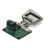
The finished result of the assembly is a transparent OLED arrangement with an XIAO M0 Board connected to it. It also has its own holder and stand, making prototyping simple unless we need to connect more components to it.
I'm experimenting with graphics for my application and will utilize this Test Bench/Board to run animations and images on this display, as well as possibly run a short game on it.
Step 10: HELLO WORLD

In terms of the code, we begin by the display's Hello World function, which is displaying text on the screen.
Before uploading, you first need to download this display's library which can be download from below link.
https://github.com/olikraus/u8g2
DC, CS and RST can be assigned to any Pin, just make sure to alter them if you are using any other MCU with this screen.
#include <Arduino.h>
#include <U8g2lib.h>

#include <SPI.h>

#define OLED_DC  0
#define OLED_CS  1
#define OLED_RST 2

U8G2_SSD1309_128X64_NONAME2_1_4W_HW_SPI u8g2(/* rotation=*/U8G2_R0, /* cs=*/ OLED_CS, /* dc=*/ OLED_DC,/* reset=*/OLED_RST);


void setup(void) {
  u8g2.begin();
  u8g2.setFontPosTop();
}

void loop(void) {
  u8g2.firstPage();
  do
  {
    u8g2.clearBuffer();          // clear the internal memory
    u8g2.setFont(u8g2_font_t0_17b_tr  );  // choose a suitable font
    u8g2.drawStr(0,5,"Hello i'm");    // write something to the internal memory
    u8g2.drawStr(0,25,"TRANSPARENT");
    u8g2.sendBuffer();          // transfer internal memory to the display
  } while( u8g2.nextPage() );
  delay(2000);
}
Step 11: Common Icon

Next is the Common Icon code which comes in the example sketches of this display's library.
This design demonstrates how we can use this display to display graphics and animations. It displays symbols and icons in a series and they look quite fantastic.
#include <Arduino.h>
#include <U8g2lib.h>

//#include <SPI.h>
#include <Wire.h>

#define OLED_DC  0
#define OLED_CS  1
#define OLED_RST 2

U8G2_SSD1309_128X64_NONAME2_1_4W_HW_SPI u8g2(/* rotation=*/U8G2_R0, /* cs=*/ OLED_CS, /* dc=*/ OLED_DC,/* reset=*/OLED_RST);

void setup(void)
{
  u8g2.begin();  //init
  u8g2.setFontPosTop();  /**When you use drawStr to display strings, the default criteria is to display the lower-left
  * coordinates of the characters.The function can be understood as changing the coordinate position to the upper left
  * corner of the display string as the coordinate standard.*/
}


void loop(void)
{
	/*
       * firstPage will change the current page number position to 0
       * When modifications are between firstpage and nextPage, they will be re-rendered at each time.
       * This method consumes less ram space than sendBuffer
   */
   u8g2.firstPage();
   for(int i = 64 ; i <287; i++){
   u8g2.clear();
   do
   {
      u8g2.setFont(u8g2_font_open_iconic_all_4x_t );  //Set the font to "u8g2_font_open_iconic_all_4x_t"
      /*
       * Draw a single character. The character is placed at the specified pixel posion x and y.
	   * U8g2 supports the lower 16 bit of the unicode character range (plane 0/Basic Multilingual Plane):
	   * The encoding can be any value from 0 to 65535. The glyph can be drawn only, if the encoding exists in the active font.
      */
      u8g2.drawGlyph(/* x=*/0, /* y=*/16, /* encoding=*/i);
      u8g2.drawGlyph(/* x=*/48, /* y=*/16, /* encoding=*/i+1);
      u8g2.drawGlyph(/* x=*/96, /* y=*/16, /* encoding=*/i+2);
   } while ( u8g2.nextPage() );
   i = i+3;
   delay(2000);
  }
}
Step 12: PYRAMID TEST SKETCH

The final concept we will try is a pyramid animation that appears to move in three dimensions. This is only an illusion; nothing is truly moving into three dimensions. Nonetheless, it is important to note that the refresh rate of this screen appears to be promising.
#include <Arduino.h>
#include <U8g2lib.h>

#include <SPI.h>
//#include <Wire.h>

#define OLED_DC  0
#define OLED_CS  1
#define OLED_RST 2

U8G2_SSD1309_128X64_NONAME2_1_4W_HW_SPI u8g2(/* rotation=*/U8G2_R0, /* cs=*/ OLED_CS, /* dc=*/ OLED_DC,/* reset=*/OLED_RST);


//2D array: The coordinates of all vertices of the tetrahesome are stored
double tetrahedron[4][3] = {{0,30,-30},{-30,-30,-30},{30,-30,-30},{0,0,30}};
void setup(void) {
  u8g2.begin();
}

void loop(void) {
  /*
       * firstPage will change the current page number position to 0
       * When modifications are between firstpage and nextPage, they will be re-rendered at each time.
       * This method consumes less ram space than sendBuffer
   */
  u8g2.firstPage();
  do {
  //Connect the corresponding points inside the tetrahethal together
  u8g2.drawLine(OxyzToOu(tetrahedron[0][0], tetrahedron[0][2]), OxyzToOv(tetrahedron[0][1], tetrahedron[0][2]), OxyzToOu(tetrahedron[1][0], tetrahedron[1][2]), OxyzToOv(tetrahedron[1][1], tetrahedron[1][2]));
  u8g2.drawLine(OxyzToOu(tetrahedron[1][0], tetrahedron[1][2]), OxyzToOv(tetrahedron[1][1], tetrahedron[1][2]), OxyzToOu(tetrahedron[2][0], tetrahedron[2][2]), OxyzToOv(tetrahedron[2][1], tetrahedron[2][2]));
  u8g2.drawLine(OxyzToOu(tetrahedron[0][0], tetrahedron[0][2]), OxyzToOv(tetrahedron[0][1], tetrahedron[0][2]), OxyzToOu(tetrahedron[2][0], tetrahedron[2][2]), OxyzToOv(tetrahedron[2][1], tetrahedron[2][2]));
  u8g2.drawLine(OxyzToOu(tetrahedron[0][0], tetrahedron[0][2]), OxyzToOv(tetrahedron[0][1], tetrahedron[0][2]), OxyzToOu(tetrahedron[3][0], tetrahedron[3][2]), OxyzToOv(tetrahedron[3][1], tetrahedron[3][2]));
  u8g2.drawLine(OxyzToOu(tetrahedron[1][0], tetrahedron[1][2]), OxyzToOv(tetrahedron[1][1], tetrahedron[1][2]), OxyzToOu(tetrahedron[3][0], tetrahedron[3][2]), OxyzToOv(tetrahedron[3][1], tetrahedron[3][2]));
  u8g2.drawLine(OxyzToOu(tetrahedron[2][0], tetrahedron[2][2]), OxyzToOv(tetrahedron[2][1], tetrahedron[2][2]), OxyzToOu(tetrahedron[3][0], tetrahedron[3][2]), OxyzToOv(tetrahedron[3][1], tetrahedron[3][2]));
  // Rotate 0.1°
  rotate(0.1);

  } while ( u8g2.nextPage() );
  //delay(50);
}
/*!
 * @brief Convert xz in the three-dimensional coordinate system Oxyz
 * into the u coordinate inside the two-dimensional coordinate system Ouv
 * @param x in Oxyz
 * @param z in Oxyz
 * @return u in Ouv
 */
int OxyzToOu(double x,double z){

   return (int)((x + 64) - z*0.35);
}


/*!
 * @brief Convert the yz in the three-dimensional coordinate system Oxyz into the v coordinate inside
 * the two-dimensional coordinate system Ouv
 * @param y in Oxyz
 * @param z in Oxyz
 * @return v in Ouv
 */
int OxyzToOv(double y,double z){
    return (int)((y + 35) - z*0.35);
}


/*!
 * @brief  Rotate the coordinates of all points of the entire 3D graphic around the Z axis
 * @param  angle represents the angle to rotate
 *
 *  z rotation (z unchanged)
    x3 = x2 * cosb - y1 * sinb
    y3 = y1 * cosb + x2 * sinb
    z3 = z2
 */
void rotate(double angle)
{
  double rad, cosa, sina, Xn, Yn;

  rad = angle * PI / 180;
  cosa = cos(rad);
  sina = sin(rad);
  for (int i = 0; i < 4; i++)
  {
    Xn = (tetrahedron[i][0] * cosa) - (tetrahedron[i][1] * sina);
    Yn = (tetrahedron[i][0] * sina) + (tetrahedron[i][1] * cosa);

    //Store converted coordinates into an array of coordinates
    //Because it rotates around the Z-axis, the coordinates of the point z-axis remain unchanged
    tetrahedron[i][0] = Xn;
    tetrahedron[i][1] = Yn;
  }
}
Step 13: What's Next

Overall, the test bench was successful, and we can now use it to make a variety of other things. I'm currently working on using the test bench to run a brief animation video on the display. After that, I'll try to run a game like Space Invaders on it by manually adding buttons to XIAO Pins, since I accidentally left out the breakout pins for XIAO I/O Ports.
These revisions can be added on Version 2 of this setup.
This is it for today folks.
Special thanks to Seeed Studio for providing the XIAO Board and PCBs for this project, Check them out if you want to purchase any type of electronic module or development board from their website, they also have PCB and PCBA services.
Leave a comment if you need any help regarding this project.
Peace.

![Tim's Mechanical Spider Leg [LU9685-20CU]](https://content.instructables.com/FFB/5R4I/LVKZ6G6R/FFB5R4ILVKZ6G6R.png?auto=webp&crop=1.2%3A1&frame=1&width=306)


