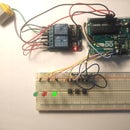
Introduction: Understanding the Pull-up/Pull-down Resistors With Arduino
With this little test I hope you'll understand why the pull-up (and pull-down) resistors are needed in digital circuits like in Arduino.
With a pull-up resistor and with the button unpressed you make a logic state ON and with the button pressed you make a logic OFF.
With a pull - down resistor and a pressed button you make an ON logic state and OFF logic state when its unpressed.
Make the above pull-up circuit and try the code. You'll see the LED flickering or less bright.
Pressing the button and you see now the LED turned normaly on (fully bright). Turning off the button and the LED its flickering again.
/*Pull-up resistor test*/
int buttonPin = 3;
int Led = 10;
void setup() {
pinMode(buttonPin,INPUT);
pinMode(Led,OUTPUT);
Serial.begin(9600);
}
void loop() {
int buttonState = digitalRead(buttonPin); //read the state of the button input
if (buttonState == LOW) { // if the button is pressed it is low state
digitalWrite(Led,HIGH); //see flickering led or less bright
} else {
digitalWrite(Led,LOW);
Serial.println(buttonState);
}
}
Step 1: With Out the Pull-up Resistor
So why was the LED flickering? Simply the logic static of the open switch is floating so it could be either a '0' or a '1". When the button is pressed this produces a clear logic state of LOW since its grounded.
Check in the Serial monitor to see this as well The will be a serial of unstable '0' and '1' caused by the floating open situation of the switch.
Step 2: With the Pull-up Resistor
To prevent the unknown state a pull-up resistor will ensure the state on the pin is low.
Add a resistor of 4.7k* (check in step 4 the calculation of the resistor) to the circuit, and try the below code
See the led working properly with the two states LOW and HIGH.
Check in the serial monitor, when you press the button you'll get a logic LOW
and without pressing a logic HIGH
/* with the pull-up resistor*/
int buttonPin = 3;
int Led = 10;
void setup() {
pinMode(buttonPin,INPUT);
pinMode(Led,OUTPUT);
Serial.begin(9600);
}
void loop() {
int buttonState = digitalRead(buttonPin); //read the state of the button input
if (buttonState == LOW) { //pressing the button will produce a LOW state 0V
digitalWrite(Led,HIGH); //the led with turn on
Serial.println(buttonState);
} else{
digitalWrite(Led,LOW); //the led with turn off
} Serial.println(buttonState); //check in the serial monitor
}
Step 3: A Schematic Explaining the LOW - HIGH State With and Without the Pull-up Resistor
On the left you see the button the moment its beeing pressed. This gives a digital signal of the LOW state.
On the right the voltage across the pull-up resistor with the button unpressed is 5Vdc providing the digital signal of the HIGH state.
Step 4: What Should Be the Value of the Resistor?
So lets assume you want to limit the current to 1mA.
Since Vcc = 5V, using Ohms law: R=U/I => R = 5000mV/1mA => R= 5000Ω = 5k
so a resistor of 4.7k will be fine
Mostly known to be used is a 10kΩ resistor, this will need only 0.5mΑ.
Step 5: Using the Pull - Down Resistor
/*simular and the pull - down resistor */
int button = 2;
int led = 10;
int buttonState = 0;
void setup() {
pinMode(led,OUTPUT);
pinMode(button,INPUT);
Serial.begin(9600);
}
void loop() {
buttonState = digitalRead(button);
if (buttonState == HIGH) {
digitalWrite(led, HIGH);
} else {
digitalWrite(led, LOW);
}
Serial.println(buttonState);
}
Step 6: Working With Out a Pull-up or Pull Down Resistor
Check for this in another post I made here
https://www.instructables.com/id/Working-Without-a-Pull-up-Pull-down-Resistor-With-/


