

Introduction: Universal Logic Gates Implementer With Arduino


This was build as a teaching aid for electricians and electronic technicians.
Students will look up on the code how it was built, and then simply will
confirm the output of the basic logic gates or even make combinations of them,
There are 3 inputs (you can add more for your needs) so there is much more to test then just confirming the gates.
In the code are the comments to explain its functions. Have fun!
(P.S. this could little program could have futher improvment, suggestions are welcomed!)
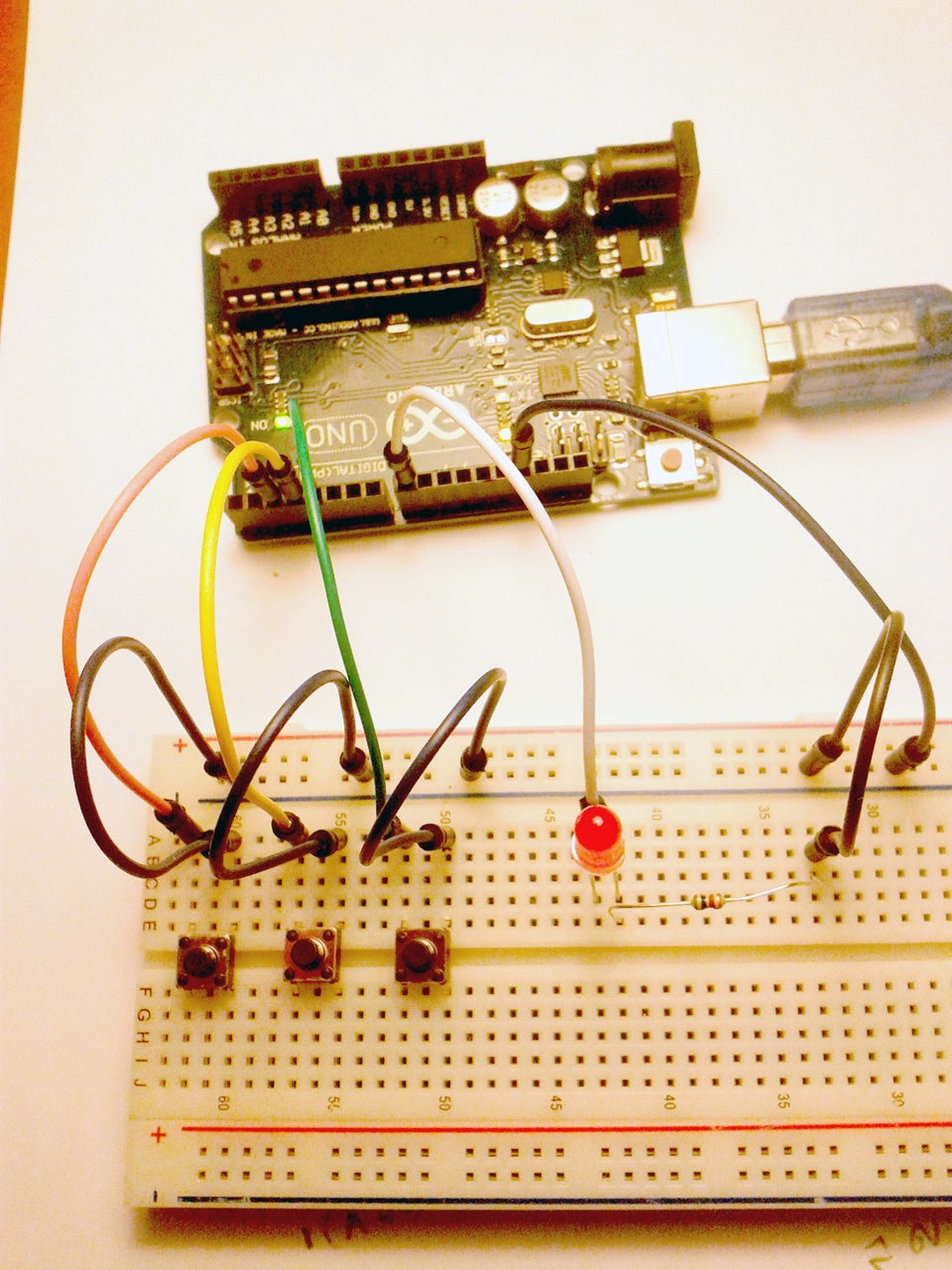
Supplies
Two (2) buttons
1 LED
1 Resistor 330Ω (Or any kind of these typical prices 150, 220, 270, 330, 470, 560Ω)
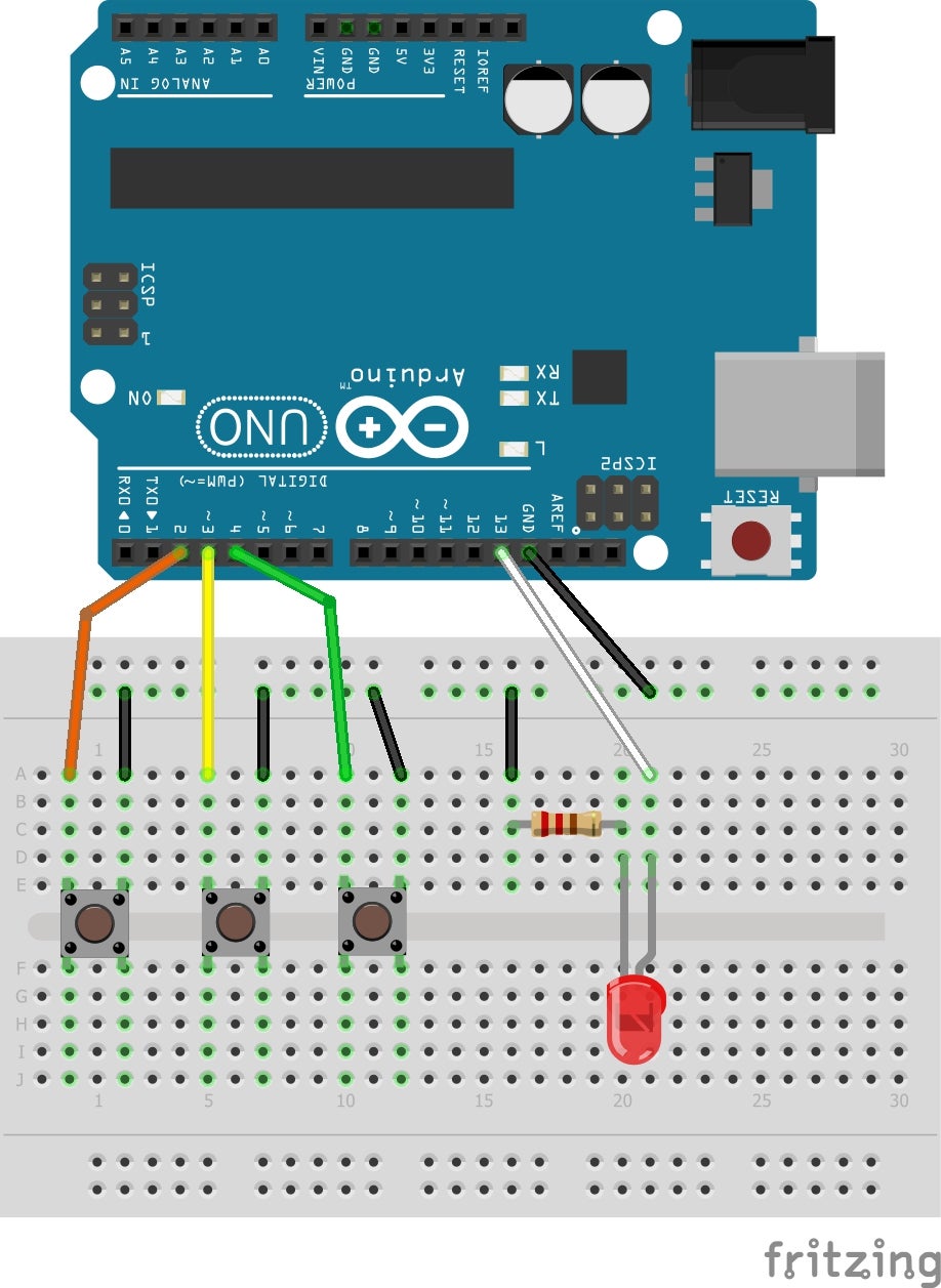
Step 1: The Code
/********************************
* Universal Logic Gates Implementer with Arduino
* Created by Panos Agiakatsikas
* Date: 22/1/2017
*******************************
The logic gates
Buffer A (Also(!A&&!A)) output [0]
NOT !A output [1]
AND (A&&B) output [0001]
OR (A||B) output [0111]
NAND (!(A&&B)) output [1110]
NOR (!(A||B) output [1000]
XOR (!A&&B)||(A&&!B) output [0110]
XNOR (A&&B)||(!A&&!B) output [1001]
*/
int buttonPin1 = 2; // Button 1
int buttonPin2 = 3; // Button 2
int buttonPin3 = 4; // Button 3
int LEDred = 13; // Out to pin
int A; // variable for input state of the button 1
int B; // variable for input state of the button 2
int C; // variable for input state of the button 3
void setup() {
pinMode(LEDred, OUTPUT); // set led as output
// set pins as inputs with internal pull-up resistor, the open button logic state for all will be HIGH
pinMode(buttonPin1, INPUT_PULLUP);
pinMode(buttonPin2, INPUT_PULLUP);
pinMode(buttonPin3, INPUT_PULLUP);
}
void loop(){
A = digitalRead(buttonPin1);
B = digitalRead(buttonPin2);
C = digitalRead(buttonPin3);
A=!A; // inverse the HIGH to LOW from the pull-up resistor
B=!B; // inverse the HIGH to LOW from the pull-up resistor
C=!C; // inverse the HIGH to LOW from the pull-up resistor
if (!(A||B)) { // put here your logic statement
digitalWrite(LEDred, HIGH);
} else {
digitalWrite(LEDred, LOW);
}
}
Step 2: How It Works: Example A
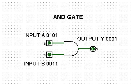
Lets say you want to test the AND Gate
In the code and the if statetment simply put the AND statement (A&&B), you must apply the truth table like this pressing the buttons an input A and B
the output Y will be on the LED [0001]
A | B | Y
0 | 0 | 0
1 | 0 | 0
0 | 1 | 0
1 | 1 | 1
Step 3: Example B
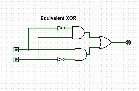
Now lets say we want to find out what is the output of the above. We must figure out the logic combinational statement here that is (!A&&B)||(A&&!B) and again insert in the if statement in the code Try it!
the output is [0110]
Step 4: Example C
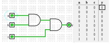
Τhis simple example has 3 inputs. We write here the boolean expression as ((A&&B)&&C)).The output y result will be like the array, and only when the 3 buttons are press simultaneously we will have the LED on.
Step 5: Example D

One more example. The picture say it clear (A||B)&&(A||C).
If you try this. the output should be
Y = [00011111]
