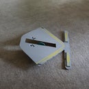
Introduction: Whistle Controlled Robot
This robot is completely guided everywhere by whistle, much like the "Golden Sonic Toy" made in 1957.
When switched on, the robot moves in the direction indicated by the illuminated arrow on the front drive wheel mechanism. When the whistle is blown, the front wheels rotate. Stop blowing the whistle and the machine will resume moving in the direction indicated by the arrow.
The drive motor in forward mode moves the robot, in reverse mode it rotates the drive wheel assembly. To make all this operate, two "one way bearings," a slip ring, sound detector and SPDT relay are required.
Supplies
(2) One way bearings
Arduino Uno
Relay, SPDT
(4) belts for wheels
DPDT switch
(2) holders for 4 AA batteries
(8) AA batteries
1/4 inch plywood--10 inches by 15 inches
(4) red led
2n3904 transistor
2 microfarad capacitor
Electret microphone
(2) 10K resistor
220K resistor
Breadboard
(2) bearing--6mm I.D., 19mm O.D.
Step 1:
Print the 3d parts and prepare to construct the robot.
Attachments
Step 2:
Insert a one way bearing into the drive wheel assembly.
Step 3:
Place a belt on the free turning (one way) drive wheel.
Step 4:
Place a belt on the motorized drive wheel. Attach the motor and solder small gauge wire to the motor.
Step 5:
Insert the wheels into the drive assembly.
Step 6:
Thread the upright shaft into the drive assembly.
Step 7:
Cut the base out of a piece of 1/4 inch plywood.
Step 8:
Insert bearings into the rear wheel assemblies. Insert wheels into the bearings.
Step 9:
Screw the rear wheels onto the plywood.
Step 10:
Wire the arrow according to the schematic.
Step 11:
Attach the arrow to the rotating base. I melted the two together using a soldering iron--glue would work as well.
Step 12:
Insert a one way bearing into the bearing holder. Screw the bearing holder to the plywood base.
Step 13:
Insert the wheel assembly into the bearing holder.
Step 14:
Attach the slip ring to the slip ring holder.
Step 15:
Push the wires through the upright shaft and attach the slip ring holder to the bearing holder.
Step 16:
Attach the wires to the diode bridge.
Step 17:
Wire the microphone and amplifier circuit on the breadboard. Attach to the Arduino and load the sketch.
Attachments
Step 18:
Wire the on/off DPDT switch and attach to the back of the base.
Step 19:
Attach the battery holders, relay and Arduino using velcro.
Step 20:
Flip the switch on and you will have a (noisy) sonic controlled robot.


