

Introduction: 220V Induction Motor Into a Brushless Generator


Hi!
In this instructable, you will learn to convert a 220v capacitor start induction motor into a generator.These are squirrel cage motors and are really robust because of which they are very cheap.
In the the video above, i tried to convert a 500W motor into a brushless generator by modifying the rotor of the generator.
Cheap PCBs : www.pcbway.com
Subscribe for Updates : https://youtu.be/oyGyNUOTu20
Step 1: Opening Up :


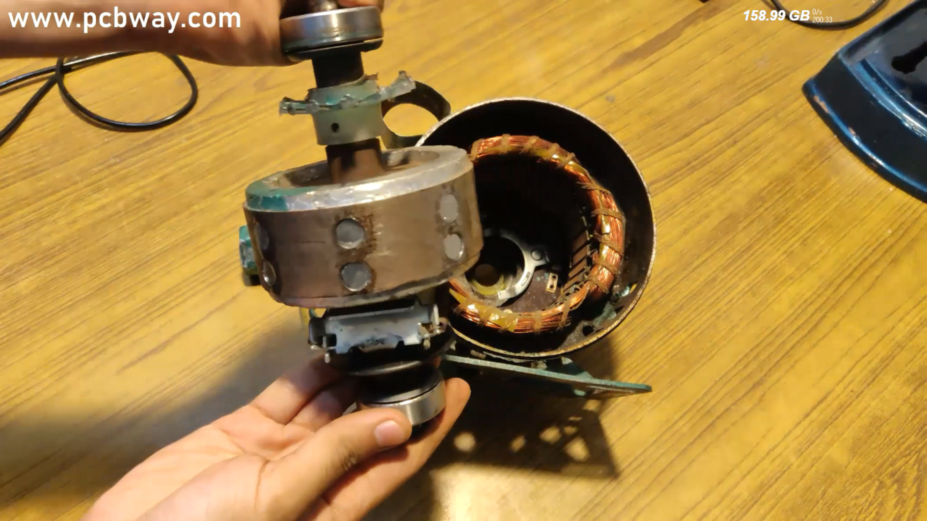
Start your project by finding an induction motor that is no longer in use but is fully working.Open up the entire motor without damaging the wiring and the bearings of the motor.
You can also go for a smaller one at first coz its gonna be easier to work on just to get an idea.
After you have successfully taken out the shaft of the motor, you will be able to count the number of armature poles.
Remember that poles are different from armature teeths and poles are always less than or equal to the number of teeths.
Cheap PCB manufacturer in China : www.pcbway.com
Subscribe for more : https://youtu.be/oyGyNUOTu20
Step 2: Rotor Modification :


First, count the number of poles on the armature example in my case there are 4 armature poles then i should place 4 poles in the rotor as well.
Though in my project as you can see in the video, i made a great mistake of doubling the number of poles on the rotor for reducing the RPM to half & because of this very reason , the induced polarities on the armature got cancelled otherwise everything is just fine and i am rectifying the problem.
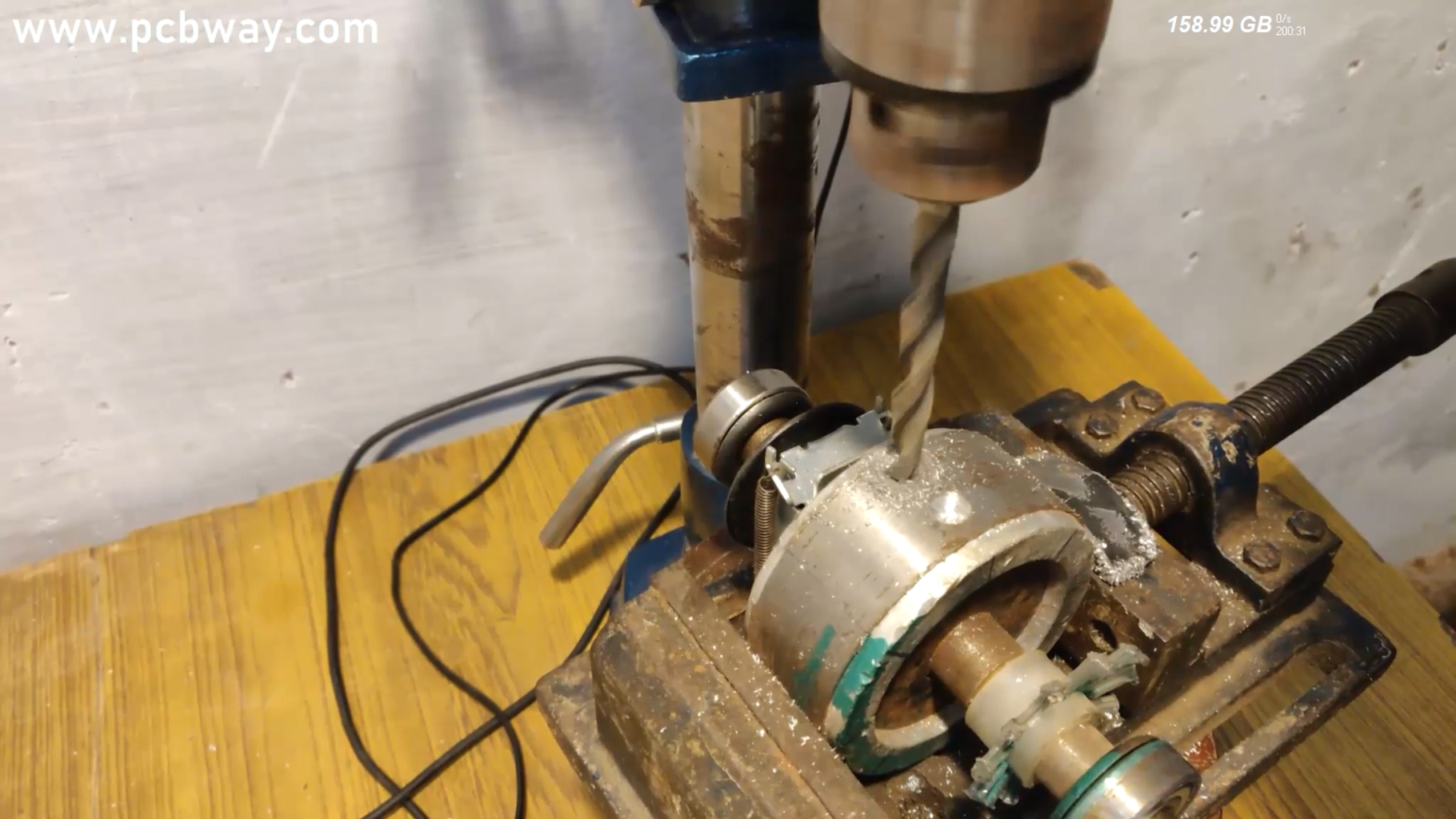
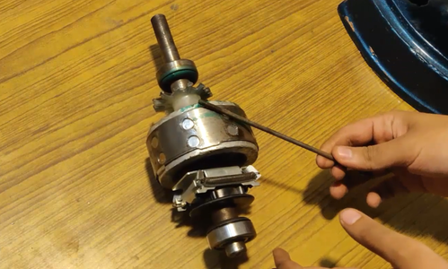
Now, mark the points on the rotor for drilling holes according to the size of the magnets you are going to use.I used 10 mm magnets and i used a 10.5 mm drill bit for proper fitting of magnets.
Low Cost PCB Assembly : https://www.pcbway.com/pcb-assembly
Full Video : https://youtu.be/oyGyNUOTu20
Step 3: Placing of Magnets :

The number of poles on the rotor will always be even and you will have to place the magnets in alternate polarity fashion like North, then South then North and so on.....
Place the magnets properly on the rotor and then fix it with a glue to counter the centrifugal pressure.
Simply slide the rotor back into the motor and and close the case carefully.
You should be left out with 4 terminals. 2 for capacitor and to for main winding of the motor.
Since the main winding is always thicker and it always has larger number of turns therefore, the power generation is gonna be higher on its terminals while lesser on the other 2.
Also guys, the the generated voltage is gonna be AC.
So that's all for today guy!!
Thanks & Regards,
Mr. Electron
Low Cost PCB Prototype : https://www.pcbway.com/pcb_prototype/
Watch Full Video : https://youtu.be/oyGyNUOTu20


