

Introduction: Arduino. Driving Industrial Equipment


Hello.
This is probably second part of https://www.instructables.com/id/Using-Arduino-in-I...
What i has in beginning
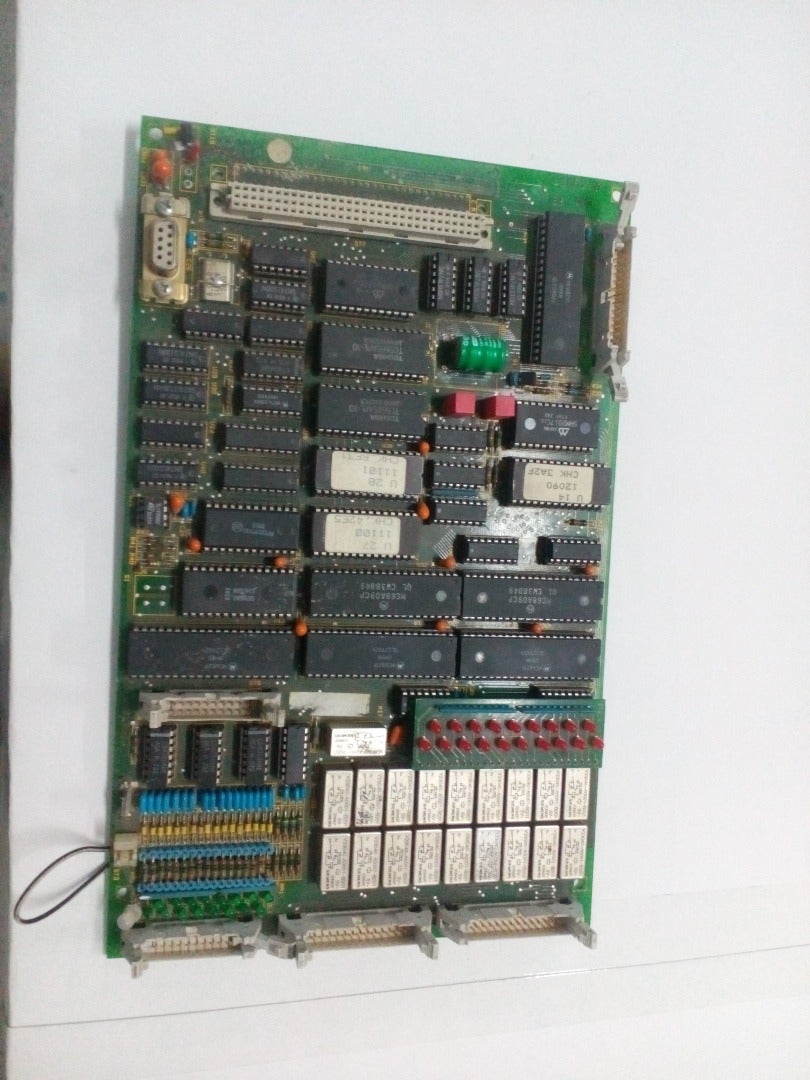
1. Fully dead/partially dead CPU on guilotonne (photo 3-4-5-6)
2. Assembled and programed arduino device from part 1 (photo 2)
3. Machine without docs
In next steps i'll describe how i ressurect this machine.
Check comments on photos
Step 1: What Signals I Have (or I Think So)


What i know that theoretically some signal exists, and.... and i tryed find and decode it
On working table
Input 1. max X slow move
2. max X stop move
3. min X slow move
4. min X stop move
5. Motor danger temp (this pin have relay logic and fully shutdown table motor to protect it from temp damage.
Relay logic mean that i can not control in any way this subsystem)
Output
1. Motor move to max
2. Motor move to max slow
3. Motor move to min
4. Motor move to min slow
5. Braking system
Razor
Input
1. Optical line protection. Work independently but i receive signal from it. This system protect human. Fully stop razor in mechanical way
2.3 lines that say what position of blade (this 3 line work in binary mode 000 001 010 011 100 101 110 111)
3. Move after cutting ready
Output
1. Button left pressed
2. Button right pressed (both buttons must be pressed in whole razor moving cycle. Left hand and right hand of operator are in safe place)
3. Advanced pressure (paper fixed and fixed before cutting)
Manual operation switch (work using 3 lines in binary mode)
000 Neutral position. All off
001 Automatic move. Encoder pc will control movement
010 Manual move (hand only)
011 Slow to max move
100 Move to max
101 Slow to min move
110 Move to min
Other 1. Output Light barier (Light sweetch that wil help operator to cut in hand only mode)
2. Oxygen pump on/off
3. Oxygen Valve on/off
Sorry if forgot about some signal.... I did 18 output lines (originally was 19) and 17 input lines + 1 power line
Step 2: Assembling

I use
1. Arduino mega I use arduino mega as i need 36+ pins
2. 2x8 relay module link to ebay
3. 1x2 relay module link to ebay
4. DC-DC LM2596 Step Down Adjustable Converter Power Supply Module link to ebay
5. One simple lcd 8x2 char screed link to ebay
Input filters was handmaded by me.
Step 3: Signals


About filters and datasheet check my previous post
On photos what signals i have without filters
Step 4: Finishing and Arduino to Arduino Connection


In the beginning to this machine was assembled encoder controller (photo 4)
On Encoder controller input
1. Encoder ch1 (input 5V via filter)
2. Encoder ch2 (input 5V via filter)
3. Encoder 1 imp/rotation (input 5V via filter)
4. Checkpoint (input 24V via filter)
5. Cutting finished (input 24V via filter)
Encoder has long vires, powered by arduino.
Output via relay
1. Move to max slow
2. Move to max
3. Move to min slow
4.. Move to min
As main controller was dead and new one was assembled i change encoder controller to
Input
4. Checkpoint (input 5V without filter) directly from controller board. Arduino-to-arduino connection. Machine line 24 V =>Filter on controller =>Arduino on controller =>arduino on encoder controller
5. Cutting finished (input 5V without filter) directly from controller board. Arduino-to-arduino connection. Machine line 24 V =>Filter on controller =>Arduino on controller =>arduino on encoder controller
Output
1-2-3-4 relay lines from Arduino encoder controller directly to pins machine controller Yes i know about ic2, spi. But i really hate to change program code that work excelent on other machines only for saving some pins unused. And i have free pins.
Project was buided in 6 days Program is really simple when you know what signals mean if someone will need this code than i'll attach it. 5 days i decode input signals and check what it mean.
On next my instructale i describe how i repair Printing press.....

Participated in the
Robotics Contest 2016


