

Introduction: Arduino Powered Three Arm Bubble Machine


Some time ago I liberated several ball screw linear rails from the scrap bin at my workplace. I used four of them to make a CNC router. I gave a few away. I have one left. So what to do.... What to do...
MAKE A BUBBLE MACHINE!!!!
There are many home made bubble machines out there, so I wanted to create something different using the ball screw slide. Therefore what I envisioned is an Arduino version of the old I Love Lucy candy packaging skit but as a bubble machine.
So the concept was multiple bubble wand raising and lowering in a random fashion. Connected to the ball screw slide is a fan. When the wand is raised and ready for blowing, the ball screw positions the fan in front of the wand and blows the bubbles. After set time of blowing bubbles, the wand lowers to recharge with bubble solution and the ball screw slide moves to the next available ready to blow wand.
I wanted this machine to be erratic in behaviour with the wands moving randomly and the ball screw slide furiously trying to keep up.
So on with the build...
Step 1: Materials

I made this machine without too many plans, but ideas in my head. So explicit drawings really aren't available. What I'm showing are mostly build ideas. This Instructable is intended to be an idea motivator. Let's face it, who really needs an Ardunio bubble machine that costs more, is less efficient, and blows less bubbles than a commercial machine? But hey, it's cool!!!
Materials:
- (1) Linear ball screw slide (cost new about $1000)
- (1) Nema 23 or 24 stepper motor to drive linear slide (approx $50)
- (3) Nema 17 stepper motors (approx $15 ea)
- (3) Bubble wands of your choice, the same length the better
- (1) Cheap blower (an old hair dryer, heat off, would work)
- (1) Arduino UNO or other microcontroller (approx $30)
- (1) Ardunio shield (approx $5.00) (optional, but easier to wire)
- (1) 4 stepper motor drivers (approx $11 ea) (I used TB6600 drivers. They can handle 4 amps)
- (3) Nema 17 motor brackets (approx $3 ea or you can make your own)
- (1) 500 watt ATX Power Supply - (approx $45)
- (1) Relay board to interface with arduino to turn blower on and off (approx $10)
- (1) Melamine board to mount everything (approx $10)
- (1) 1/4" plywood for enclosure and cup holders.
- (1) 1" corner molding for enclosure lid.
- (3) 4" PVC pipe caps
- (~25 ft) 22/4 cable (approx $10)
- (lot) fasteners, wood glue, hot melt glue, patience, a sense of humor for doing something so idiotic, etc.
Step 2: Arduino Software

This information may be a bit early, but I wrote the software and planned out my Arduino wiring before I received my components from the various e-bay stores I used to procure materials.
This project runs four stepper motors on the same controller. Therefore to have enough pins, I couldn't use a common H-bridge and the Stepper library from the Arduino library page. After some web searches, I found the AccelStepper library from Mike McCauley.
This library is far more powerful than the Stepper library. It can handle accelerations. I can run stepper motors via several wiring schemes. I utilized pulse and direction. It can return such information as distance to go and current speed. It's a impressive piece of motion control software.
I'll refer you to the AccelStepper website to get the library and how to install it on your Arduino. Note that I originally used the Arduino IDE 1.0.5. It didn't know what to do with the code. I upgraded the IDE 1.8.1 and then it would compile,
Below is the code to run the bubble machine. I'm not a particularly accomplished coder (I'm a mechanical engineer, not a software designer), so please don't knock on it too much. I hope I've added enough comments so you can follow it.
// StepperBubble Rev 3
//
//
// Runs one stepper motor for a linear drive to move a fan to
// three positions where a bubble wand connected to a
// stepper motor moves between 0 and 90 degrees.
//

#include <AccelStepper.h>

// Define Stepper Pins

const int P1pin = 2;    //Pulse Pin - Motor 1
const int D1pin = 3;    //Direction Pin - Motor 1
const int P2pin = 4;    //Pulse Pin - Motor 1
const int D2pin = 5;    //Direction Pin - Motor 1
const int P3pin = 6;    //Pulse Pin - Motor 1
const int D3pin = 7;    //Direction Pin - Motor 1
const int P4pin = 8;    //Pulse Pin - Motor 1
const int D4pin = 9;    //Direction Pin - Motor 1
const int fanpin = 10;  //fan on digital output
const int homepin = 11; //Input pin for slide homing switch

const long Pos1=100;    // Position for Wand 1 (stepper 1)
const long Pos2=200;    // Position for Wand 2 (stepper 2)
const long Pos3=300;    // Position for Wand 3 (stepper 3)
const int down=0;       // Step position for wand down
const int up=50;        // Step position for wand up
const int homedelay=50; // Delay (ms) between steps for homing cycle)

const long pausetime=5000; // time to pause to blow air
long timer=0;              // pause timer

boolean nextpos=false;     // Is next position nextpos?

// Define some steppers and the pins the will use

  AccelStepper stepper0(AccelStepper::DRIVER, P1pin, D1pin);  // DRIVER = Step-Dir Pulses
  AccelStepper stepper1(AccelStepper::DRIVER, P2pin, D2pin);  // DRIVER = Step-Dir Pulses
  AccelStepper stepper2(AccelStepper::DRIVER, P3pin, D3pin);  // DRIVER = Step-Dir Pulses
  AccelStepper stepper3(AccelStepper::DRIVER, P4pin, D4pin);  // DRIVER = Step-Dir Pulses

void setup()
{
  pinMode(fanpin,OUTPUT);                                    // nextpos pinmode for fan enable pin
  digitalWrite(fanpin,LOW);                                  // Turn off fan

  pinMode(homepin,INPUT_PULLUP);                             // Define the homepin as digital input

  stepper0.setMaxSpeed(500);
  stepper0.setAcceleration(100.0);
  stepper0.moveTo(0);

  stepper1.setMaxSpeed(1);
  stepper1.setAcceleration(100.0);
  stepper1.moveTo(up);

  stepper2.setMaxSpeed(5);
  stepper2.setAcceleration(100.0);
  stepper2.moveTo(up);

  stepper3.setMaxSpeed(10);
  stepper3.setAcceleration(100.0);
  stepper3.moveTo(up);


  Serial.begin(115200);
  while (!Serial) {;}

// This next section "homes" the slide axis (0)

  while (digitalRead(homepin)==1){
    stepper0.moveTo(-1);
    stepper0.run();
    //delay(homedelay);

    Serial.print("     Motor 1:");
    Serial.print(stepper3.currentPosition());
    Serial.print("     HomeInput:");
    Serial.println(digitalRead(homepin));

    stepper0.run();
  }


}
void loop() {

   if      (stepper1.currentPosition()==up && nextpos==false) {        // Move fan to wand position 1 if wand 1 is up
            stepper0.moveTo(Pos1);
            nextpos=true;}
   else if (stepper2.currentPosition()==up && nextpos==false) {         // Move fan to wand position 2 if wand 2 is up
            stepper0.moveTo(Pos2);
            nextpos=true;}
   else if (stepper3.currentPosition()==up && nextpos==false) {         // Move fan to wand position 3 if wand 3 is up
            stepper0.moveTo(Pos3);
            nextpos=true;}

  if (stepper0.distanceToGo()==0 && millis()-timer <= pausetime){       // Check if fan is stopped moving
     if      (stepper1.currentPosition()==up) {
              digitalWrite(fanpin,HIGH);                                // Turn on Fan
              nextpos=false;}
    else if (stepper2.currentPosition()==up) {
              digitalWrite(fanpin,HIGH);                                // Turn on Fan
              nextpos=false;}
    else if (stepper3.currentPosition()==up) {
             digitalWrite(fanpin,HIGH);                                // Turn on Fan
             nextpos=false;}
  }

 if ((stepper0.distanceToGo()==0 && millis()-timer >= pausetime) || stepper0.distanceToGo()!=0 ){    // Reset Timer
    timer=millis();
    digitalWrite(fanpin,LOW);                                                                        // Turn off fan

    if (stepper0.distanceToGo()==0){                                    // Check if fan is stopped moving
         if      (stepper1.currentPosition()==up) {
                  stepper1.moveTo(down);
                  nextpos=false;}
        if (stepper2.currentPosition()==up) {
                  stepper2.moveTo(down);
                  nextpos=false;}
        if (stepper3.currentPosition()==up) {
                 stepper3.moveTo(down);
                 nextpos=false;}
   }
 }


 if  (stepper1.currentPosition()==down ) {           // Send wand one up, if it's down
      stepper1.moveTo(up);
      stepper1.setMaxSpeed(random(2,20));
      }
if  (stepper2.currentPosition()==down ) {           // Send wand one up, if it's down
      stepper2.moveTo(up);
      stepper2.setMaxSpeed(random(2,20));
      }
if  (stepper3.currentPosition()==down ) {           // Send wand one up, if it's down
      stepper3.moveTo(up);
      stepper3.setMaxSpeed(random(2,20));
      }
 //  if  (stepper2.currentPosition()==down ) {stepper2.moveTo(up); stepper2.setMaxSpeed(random(2,100);}  // Send wand two up, if it's down
 //  if  (stepper3.currentPosition()==down ) {stepper3.moveTo(up); stepper2.setMaxSpeed(random(2,100);}  // Send wand three up, if it's down

 stepper0.run();
 stepper1.run();
 stepper2.run();
 stepper3.run();

  Serial.print("Motor 0:");
  Serial.print(stepper0.currentPosition());
  Serial.print("     Motor 1:");
  Serial.print(stepper1.currentPosition());
  Serial.print("     Motor 2:");
  Serial.print(stepper2.currentPosition());
  Serial.print("     Motor 3:");
  Serial.print(stepper3.currentPosition());
  Serial.print("     Fan:");
  Serial.println(digitalRead(fanpin));

}
}
Let's talk about sections of the code:
Initialization
- Include the AccelStepper library
- First I define the pins.
- Define some global variables. A few variables you need to change based on your build:
- Up - number of steps to rotate the motor 90 degrees. 50 for a 1.8 deg / step motor.
- Pos1 - where wand one is in real life.
- Pos2 - where wand two is in real life.
- Pos3 - where want three is in real life.
- pausetime - How long (ms) you want the fan to blow
- homedelay - How long (ms) between steps when homing the stepper0 axis.
- Define the motors
Under Void setup()
- Set my stepper limits and initial conditions.
- Home the slide. The motor will go one step, delay, then check for the home switch. If the home switch isn't met, then go another step.
- The Serial.begin is there to monitor the motor positions through the serial. It's a troubleshooting tool and uncomment if you have issues.
Under Void loop()
- Determine if each wand is up or down. If a wand position is up, move the fan to that position.
- If the linear rail has moved to it's next position, determine that position and turn the fan on.
- Reset the pause timer if the fan has blown enough. This is important. You cannot use delay() because that would freeze the entire program. Pausing one motion cannot inhibit the movement of other motions.
- If the wand is down, send it up at a random speed (pulses per second). In the random, set the max and min pulses per second for each wand motor. The values here are guesses of initial conditions.
- Enact Accelstepper to move the motors a pulse.
- Uncomment to see the positions in the serial monitor.
Step 3: Electrical Connections

When the hardware is installed in the later steps, wire the system to the above schematic.
The thing to remember is when it comes to steppers:
Power Supply -> Controller -> Driver -> Motor.
The power supply provides power for the entire system.
The controller (Arduino Uno in this case) controls the motor pulses and direction.
The driver amplifies the 5 volt signal from the controller to the 24 volt motor voltage. It also converts the step and direction pluses into the proper pulses for the motor windings.
The motor does what a motor does.
I can be a lot of wires and it can be duplicitous, but that's how it goes...
Attachments

Step 4: Bubble Wands to Wand Motors


The bubble wands need attached to the three Nema 17 motors. Considering that I have the equipment, I used a lathe and a milling machine to make aluminium brackets to mount the wands. Depending on your access to equipment, you could 3D print the brackets, make them out of wood, or just glue them.
It's important that the wand length be fairly consistent between the three motors so that when the fan reaches them, the fan is more or less centered on each wand.
Step 5: Mounting the Ball Screw Slide Motor

I had a NEMA 23 motor sitting around that I used to drive the ball screw slide. Fortunately the slide already had a motor mounting bracket attached. (My workplace really tossed out some great stuff). Unfortunately, I didn't have a coupling to go from the motor shaft to the ball screw shaft.
As stated before, I do have machine tools though. So I made a rigid coupling.
A rigid coupling isn't ideal, but will work here. When making a rigid coupling, two things are of importance:
- Drill out the shaft in one setup. Every time a part is removed from the lathe, the centering can get a little off. This required two bores (1/4" & 5/16" diameters). So I drilled and reamed for the 1/4" first, then drilled and reamed for the 5/16" second, but in the same set up.
- Assemble the system and check for binding before bolting the motor to its bracket.
Step 6: Mounting the Ball Screw Slide


I positioned the ball screw slide onto the melamine board so that I'd have enough room for the power supply, drivers, etc. At the time when I wrote this, I hadn't actually received those parts in the mail, so my placement was a guess.
I used the ball screw slide itself as a template to locate the mounting holes. Also, with a spade bit I counterbored the backside of the board so the fasteners would be recessed into the board and the board would sit flat
Step 7: Power Supply - Background and Theory

It may seem a bit odd to have an entire step dedicated to a section to the power supply. There are a multitude of Instructables on how to convert an ATX power supply to a benchtop power supply. So I guess it's of some importance to have that information here as well.
I decided to use a computer power supply to power this contraption. There are two advantages to this:
- They are very easy to find locally.
- They have a multitude of taps to get various voltages.
The Arduino needs a five volt supply. It can take up to 12vdc, the board's regulator will just dissipate the extra energy.
The motors can handle up to 48 volt. I ran them at 24 volts.
Here's the catch:
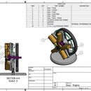
An ATX power supply doesn't have a 24 volt tap!!!
So how does one handle this? Look at the above graphic. You can see that motherboard connector has the following voltages:
- +3.3V
- +5.0V
- +12V
- -12V
- -5V (maybe, depends on the power supply)
- COM (ground)
And in those voltages is the key. The term "ground" or "common" is used as a reference. A motor or controller doesn't care what the "ground" is, as long as its common to all devices. Therefore, I used my -12 volt tap as common for the motor drivers allowing the following voltage potentials are available:
- 0V (-12 connected to -12)
- 7V (-5 connected to -12)
- 12V (COM connected to -12)
- 15.3V (+3.3V connected to -12)
- 17V (+5V connected to -12)
- 24V (+12 connected to -12)
Of course one would never connect these taps together without a load in between (resistor, motors, etc) or the thing would short and possibly blow up.
The motor drivers have two sections, a high (driver) voltage and a low (control) voltage. As far as I can tell, they are isolated from each other with their own commons. Therefore I can connect the microcontroller and the driver low voltage side to +5V and the power supply's COM and the motor driver high side to +24V and -12V for 24V difference.
Other notes. An ATX power supply doesn't have an actual switch to turn on the supply. It has the green PS_ON# wire which would usually connect to a computer's motherboard which is then wired to a computer's on/off button. Connecting this green wire to a black COM wire will turn the power supply on. This was great for the bubble machine, because it became the place to wire the E-Stop button which then acted as the power switch.
Step 8: Electrical Enclosure


There's a lot of pictures here for good reason. There's a lot of mini-steps to making the enclosure.
First I clamped the base into my CNC router and milled a 1/4" wide x 1/4" deep rectangular slot for the enclosure sides to engage.
Second, I cut several pieces to make the lid. I've never been great at miter cuts. I guess I'll just keep trying until I get it right.
Third I used used wood glue to glue the enclosure sides. When the sides were tacky, then I glued the lid together and clamped it into position.
After the wood glue cured some more, I filled in the cracks with some hot melt glue.
With the enclosure curing, I began to tackle the beginning of installing the electronics. I used some pieces of wood to block the power supply into position.
I was pained to cut up a brand new power supply, but that's what I bought it for. Taking the green (power on) wire and a common (black) wire and wiring it to a cheap E-stop switch, I have the system killed when the button is pressed.
After that it was just a matter of placing the various components (drivers, Arduino, etc.) and wiring it up.
Step 9: Home Switch

The linear slide needs to home itself prior to blowing bubbles. This is essentially a robot / CNC machine after all. So I acquired a plunger type, Honeywell style microswitch. I found a stainless steel bracket laying around my shop. After drilling a few holes and a few screws. The machine will be able to home this axis. (I apologize for the photo. A black switch against a black background component just doesn't show up well.)
As for the other axis, it's far more simple. Just manually push them down into bubble solution before turning on the machine. I could have added home switches for the bubble wand motors. And if this was going to be permanent machine instead of just a diversion,I would have. It's not. It's for a 2017 Maker Faire display. At the end of the season, I'm going to disassemble this thing and scrap the wooden portions. Quite simply home sensors for the bubble wands was more trouble than what it was worth.
Step 10: Mounting the Wand Motors

Once the brackets I ordered finally were delivered, it was a pretty easy job to use wood screws to attach the motors to the base board.
Step 11: Mounting the Fan


Mounting the fan was a fairly simple affair.
The first step was to cut out a wooden plate to mount the fan. I used my CNC router for this. Then I measured the mounting hole spacing on the linear slide and manually drilled the hole pattern.
After bolting down the plate, I then fabricated a simple bracket out of some aluminum strip I had laying around. Then I was able to secure the fan to the plate.
Step 12: Trials and Tribulations (aka: the Low Point of "Every True Hollywood Story" or Build/Fix It Reality Show)

As expected as building a machine without any real plans, there were issues. But April 14, 2017 was particularly painful and frustrating.
- I didn't build my enclosure large enough, so I had to leave the fan relay off. This isn't the end of the world. The fan would just run continuously. It's not ideal for the sensory impact of the machine, but actually it would be easier on the fan motor (steady state running vs short cycling).
- Enabling the serial connection was a bad, bad idea. An open serial connection slows down the whole system to the point where the motor step rate was limited by the serial data. Removing the serial data greatly sped up the motors, but made debugging much more difficult.
- The linear slide motor doesn't have enough oomph to move the fan back and forth quickly enough. If I increased the step rate above 800 steps per second, the motor would stall. The root cause of this isn't the motor size, it's not really under much load. The issue is the 24volts. It really needs more. If you want speed, up the voltage. If you want torque, up the amps. But I'm stuck with my 24 volt power supply. My router motors, which run on 36V and are "triple stack," run the same model slide much, much faster.
- Because of the linear slide speed issue and the fact I'm a lousy programmer, I couldn't get the jittery, uneven action I was looking for in the design. Lucille Ball, my tribute to you had failed.
- And lastly: I blew up the Arduino. Because of a wiring snafu, I put too much voltage on it. It worked ok for a while then it didn't. No satisfying blue smoke, but the Arduino was certainly dead. Upon further pondering I realized that I originally wired the system incorrectly the Arduino's ground as -12V. Oops. So what's another $25 for a new Arduino? (This project's been over $200 so far....)
YET, I SHALL PERSEVERE!!
That brings me to the next step.....
Step 13: Recovery!!!

Now knowing I wasn't going to get the machine to work as I originally imaged, it was time to figure out what to do.
So, the result was to change the action. The new, revised, goal was to have the fan move to wand position one, two, or three in a random fashion. Once the fan reaches that position, the corresponding wand would raise for bubble blowing then retract. The fan would then travel to another position.
This required a rewrite of the software, included here is the .ino file.
Attachments

Step 14: Wand Cups


As the wands lower down, they need to recharge with bubble solution.
I purchased three 4" PVC pipe caps and used the lathe to cut them down to a more useful height.
I didn't want the cups to move around, so I needed to secure them, but I wanted to remove them for cleaning. Therefore I used the router to make from wooden rings for the cups to sit into. Securing the rings with a couple of brass wood screws and this portion was complete.
Step 15: Finished!!!

So what to take away from this endeavour?
1. A project will always cost more money than you originally think.
2. You will have issues. A real test of character is how you respond and over come them.
3. Don't put too much voltage on an Arduino.
4. Direct shipping from China can take several weeks.
5. Know your limitations. (For me, it's my programming abilities)
5. Writing an Instructable as the machine is built will result in a longer and much more detailed Instructable.

Participated in the
Robotics Contest 2017

Participated in the
Microcontroller Contest 2017


