

Introduction: Arduino Shooting Game Arcade


Hello Friends,
Welcome to my shooting range.
This instructable is all about making your own Shooting Game within your budget. This setup cost me only approx. 15$ (1000INR)
The project is now of alpha version.The animations and game, you are seeing in videos are preliminary. You can do many thing that you can imagine.
The game you see in video is as follow-
To start game shoot any sensor. Difficulty block will start. Green part (Left) is easy and as moving to the Red (right) difficulty increases. Difficulty is nothing but time between two rounds. Then there will be 10 rounds. So now just play with your friends and Enjoy....
Modifications can be and to be done -
- 2 player mode
- Set different no. of rounds
- Different and attractive animations and many more.
- Also another idea - circular target with 6 circles of sensor.
Also I tried to capture lots of images wherever possible, this will give you more clear idea about every step.
Hope you like my shooting range. Comment below if any suggestion, question, or anything.....
Now let's see how to make it.
Step 1: Gather Some Material


Electronics
- LED
- Super Bright Red LED * 150 nos
- RGB LED * 12 (Common Cathode)
- IC & Transistors
- MAX 7219 ic * 2
- 2N2222 npn transistors * 6
- Resistors
- 220 Ohm * 100
- 1M Ohm * 6
- 10K Ohm * 2
- Capacitors
- 10uF (electrolytic) * 2
- 100nF (Disc) * 2
- Other
- PCB large size * 3
- IC Socket 24 pin * 2
- 2 pin female header * 6
- Headers - As per requirement
- More connectors as per requirement.
Hardware
- Laser Pointer
- Toy Gun (Or simply laser gun)
- Glass Bowls * 6
Tools
- Soldering iron, metal & flux
- Hacksaw blade or any cutting tool
- ................ this space if any required later
Some items may not be listed such as connectors. Take them as you need.
And the cost does not include cost of Arduino Board also price may vary from place to place.
Step 2: Here Is the Sensor !!!


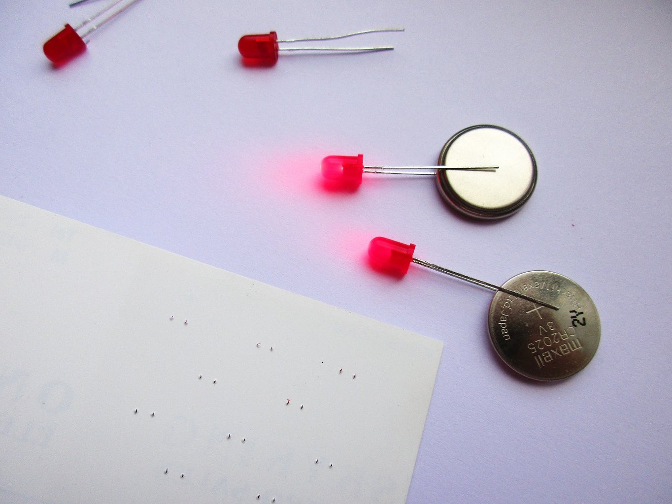
Have you wondered I had not used any photo diode, photo transistor, photo resistor and ........
The secret is LEDs. Every led emits light but also generate small voltage when exposed to light. But it's current is too low which is not useful for power generations.(such as solar). But it is sufficient for our project.
In my test, results were as follow for Red LED -
1. Dark / minimum light = 0.00 to 0.03 Volts
2. Bright light = 0.15 to 0.5 Volts
But the magic is here - when exposed to laser
3. Laser Light = 1.5 Volts max & 0.5 to 1.2 Volt regular
(green and yellow led also works fine)
And main thing - Use super bright LEDs.
So first of all test your LED whether it is generating usable voltage or not.
Internet is a huge world where you can get anything like I got this one, search if you want more details.
Step 3: Block Diagram. How It Works !!!

Here is the overall block diagram of this project.
Sensor modules - Sensor modules are connected to arduino's analog pins. We have 6 analog i/p pins so I made 6 modules. And Because there are 6 modules so connected 6 modules to 6 digital output pins. Laser triggers the LED module and send signal to arduino. LEDs glow by arduino's digital o/p pins via transistor module. Let's see it in next step. That's all about sensor modules.
RGB circuit - Second part is of indication, decoration purpose that I used rgb led's. I think you may know about MAX 7219 ic, if not then it is used for led matrix, multiple 7 segment displays as driver & uses only 3 arduino pins. I used this ic because - 1) Limited no. of arduino o/p pins 2) Code & connections are simple 3) easy to use . This ic is the most costly component in whole project.
Matrix - Third and last part is display module (Matrix). I made one 8 X 8 led matrix (As we are already using much LED's then why to buy separate led matrix display.) So made one matrix of 64 LED's. It also uses one more max 7219 IC as driver. It takes signal from previous 7219 IC. So this saves arduino pins
And these all circuits and modules are controlled by the Boss - The Arduino.
(You can use raspberry pi or any other micro-controller )
Step 4: LED (Sensor) Input As Well As Output

Now I think you had understood the overall circuit and LED working as a sensor.
Now Let's see How LED (Sensor panel) is acting as input as well as output.
To measure voltage generated by LED, we are connecting LED's +ve terminal (Anode) to the arduino's analog input pin. And another -ve terminal (Cathode) to the common ground. This is how arduino measures the voltage. But while testing this, I found that my readings are floating. (you can search on google - Arduino floating problem). So I connected one resistor of about 1 Mega Ohm (R3) in between arduino's analog pin and ground.
Now to lit the LEDs, we need to power these LEDs. For that I connected one switching transistor 2N2222 as shown in figure. It's Base is connected to the arduino's digital output pin. When it is HIGH transistor will give 5V supply to LED panel. To limit supply current to LEDs , connected 220 Ohm resistor to each LED. (Each - because there will not be problem if one LED take more current and another less) So the each LED will take same current of about 11mA. Also to limit digital pin supply of arduino, connected 220 Ohm resistor (R1) in series between base and digital pin.
IS THIS SAFE TO GIVE HIGH CURRENT AT ARDUINO'S ANALOG I/P PIN ???
The answer is YES but...
ANALOG I/P PINS SHOULD BE SET TO INPUT ONLY AT ALL CONDITIONS
If you give high current to analog input pin to read, though it will take only few nano Ampere current. Because is has high impedance(resistance). But as i said, that pin should be set for input only. If you set it for output it will supply large current. But arduino can only supply 40mA current per pin. So your arduino will be damaged. If accidentally pin is set as output, then to limit current I connected 220Ohm resistor (R2). But I had not taken any risk and tested it. Also I don't know what will happen due to reverse flow of current. So better way keep analog pins to input only.
Reference - http://forum.arduino.cc/index.php/topic,21010.0.ht...
Step 5: Let's Make Sensor Panels

Sensor panel is nothing but pattern of LEDs connected in parallel.
We can use any no. of LEDs in parallel.
To give same supply current to individual LED, each LED should be connected via on current limiting resistor as said in previous step.
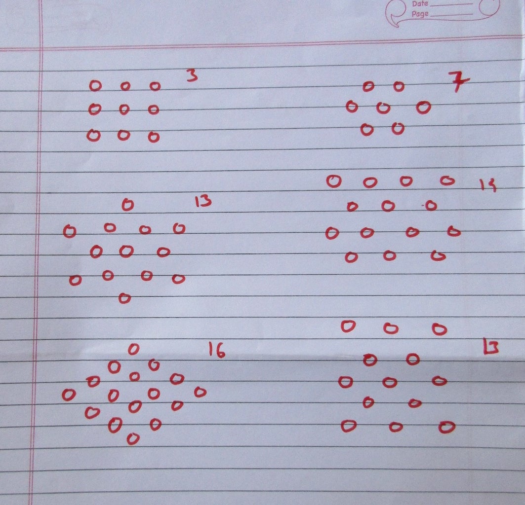
You can connect any number of LEDs in each panel. So this step involves
- How many sensors you want.
- What should be pattern of LEDs arranged.
- Simply - sensitivity towards laser beam
So in this projects I tried many no. of patterns, to give more sensitivity towards laser, to increase sensor panel size & mainly to reduce no. of LEDs per panel.
Also there should be minimum void between LEDs, so that you will not miss any shot.
One more thing to consider - How much is the distance between laser gun and targets.
I choose 3-2-3-2-3 LED pattern consisting of 13 LEDs for our project. This worked well.
As you increase LEDs, current required to lit panel increases. So check that transistor can sustain the current.
Step 6: Preparing PCB


Now let's start making our sensor panels.
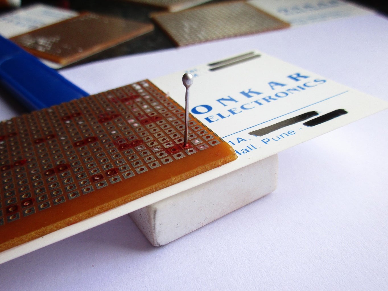
- Cut the PCB in proper size of about 5cm*5cm. You can use Large size PCB. It will give 6 required PCB directly.
- Take any white card/paper (you can see I used back side of visiting card). This white surface will somewhat disperse the laser beam (Yeah it should not reflect light).
- Then apply glue on PCB & stick it on card as you can see in picture.
- Mark Holes where we are going to place LEDs.
- Let glue be semi dry.
- Now place eraser under card and insert a pin in marked Holes.
- After required holes are made, Cut the card in required size.
Step 7: Check LED, Beware of Pins !!!

Now further step is to insert LEDs in panel.
But first check LEDs. whether they are glowing are not. Also don't rely on pins. ie. longest terminal is +ve terminal and short terminal as -ve. (We always use this). But some LEDs may be faulty. As I found 3-4 LEDs in total lot faulty having reverse terminal. Also there were 2-3 not working. So first test all of then when you get the LEDs, then use it. Because it is very very difficult to remove any LED after you solder it.
So things to check -
- Led is working or not.
- Is it dim than others?
- Their terminals are correct or not.
There is one easy trick to find -ve terminal. The side of the -ve terminal is slightly flat. You can see it & also feel it by your fingers.
Step 8: Soldering LEDs (Cathode)


Refer images for this and next steps.
- First insert checked LEDs in holes made.
- Cut Anode (+ve terminal, Longest pin) to about 5mm to 10mm.
- Bend cathode of every LED in one direction(right)
- Solder every line.
- Then bend ends of every line at 90 degree with nose plier and take only one common ground terminal at outlet.
- Solder rows together.
- Simple - Now half part is over.
The main purpose is to take out one common ground.
Step 9: Soldering LEDs (Anode)


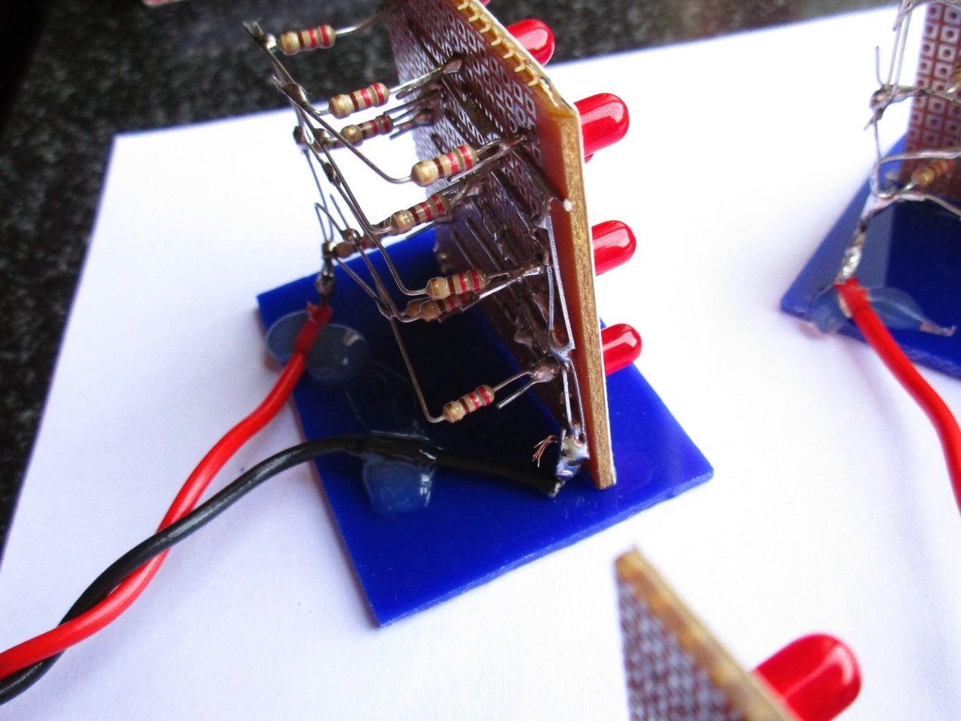
- Take resistors(220Ohm) and cut one side leaving approx. 10 mm pin.
- Insert the shortened pin in the hole as shown in 2nd image.
- Solder it.
- Do this for all LEDs.
- Now as that of cathode, Bend the other ends of resistor in one direction (this time to the Right).
- Perform same thing and soldering as done previously for cathode.
- Take out only one common anode.
- Check every LED glows or not.
Wherever possible try to insert resistor in hole. This makes it easier to solder. When not possible as happened to me several times, that time hold resistor upright with clamp/plier. Then carefully solder it.
Last image shows what I made in my first attempt. Looks creepy....
Step 10: Testing Modules


Now to proceed further it is good to test sensor panel first.
First give 5volt to panel and check all LEDs are glowing or not.
Then make one simple transistor circuit on breadboard as explained earlier.
You can use any alternative switching transistor which can handle current required for one panel. For this what we had made requires about 150mA current. 2n2222 also known as pn2222 is best. Current increases as no. of LEDs increases.
Upload arduino code given below.
To test it put laser beam on panel. panel should lit.
If it does not, then in program reduce 'sens' value.
Also you can sensitivity by changing sens value.
This sens value is not applicable for final assembly.
Attachments

Step 11: Final Touch to Sensor Panels


In this step, we are going to make base/case for our sensor modules.
First attach wire to module. One thing I forget to show you, is to attach 2 pin header (female) pin to each modules. For each module consider the length of wire required and then attach header pin at the end.
Then as you can see attach base to module. I used acrylic sheet base. I want to make box for each modules, but that won't get correct and was looking bad. So tried this simple one. disadvantage of this is, it is not safe, if it fall down. We need to take care of it.
So try what else you like or make simple like this one.
Step 12: Let's Make Transistor Panel


It's very easy to build circuit. I uploaded some images so you can relate them.
There are six transistor circuits (that you made for testing sensor modules) for six Sensor modules.We can supply whole circuit at common terminal taken out at left side.
Jumper wires are used to connect each part's +ve and ground.
Step 13: MAX 7219 Connections


So now let's move towards Display circuits.
IC 7219 is a 24 pin IC. It operates on 5V.
Pins of 7219 are as follow -
- Din - Takes data from arduino or from previous 7219.
- CLK - Connected to arduino.
- Load - These pin is also connected to arduino.
- Dout - It sends data to next 7219 IC
- segDP, segA, segB, . . . . segG - These are +ve pins ie. supply pins. These are connected to anodes(+ve) ot the LEDs. They can supply maximum 40mA current per pin. There is no need of resistor in series to limit current. These pins connects columns of the matrix.
- DIG0, DIG1, DIG2, . . . . DIG7 - These are -ve pins. Are connected to cathodes(-ve) of the LEDs. These pins connects rows of the matrix.
- +V or +5 - +5volts supply pin of IC
- GND - ground pins of IC
- Iset - This pin is important. This controls the brightness(current) of LEDs. There are two option in this IC to control brightness 1)In program you can set brightness 2) Changing resistor at this pin. Generally 10K Ohm resistor is connected between this pin and supply. Care should be taken while selecting resistor, it may damage IC due to over current.
Connections-
This IC does not require much components. Just 2 capacitors (100uF electrolytic and 10nF normal disc) between supply and ground. One resistor of 10K Ohm at Iset pin.
segDP to segG pins are connected to columns of matrix(+ve) and Dig0 to Dig7 pins are connected to Rows (-ve)
Dout is taken out for next IC.
You can easily get datasheet of 7219 IC on net.
Step 14: Matrix - Mounting LEDs & Connecting Rows


To start making Matrix Display
- Take one large size PCB board.
- Insert first LED as shown in figure.
- Bend its Cathode (-ve terminal) to one side.
- Leaving 4 holes, in 5th hole insert another LED.
- Repeat till 8 LEDs are inserted in total.
- Check if its symmetrical to board. If not then adjust LEDs.
- Solder every LEDs Cathode(-ve) and make one row.
- Similarly make new row of LED until total 8 rows are made. (new row starts leaving 4 holes down from anode pin hole of previous row, and 5th hole is required one)
Step 15: Connecting Columns


- I think you should refer image, because images will tell you more clearly how to bend anodes.
- After you bend anode, solder it and make one column.
- Repeat till all columns are made.
- After this, take wire and take out connection for each row.
Step 16: LED Matrix Circuit of MAX7219


Solder the circuit that you see in connection diagram.
I used header pins so that we can easily remove connections and to easily check matrix. These are not compulsory. You can directly solder the wires.
There are two connectors used IN and OUT. IN is used get data. and OUT sends data to next IC. Each and every pins of these IN and OUT pins are connected(shorted) except Data pin. For Out connector data is connected to Dout of the IC.
Capacitors and resistor are -
Capacitor C1 - electrolytic 10uF
Capacitor C2 - disc 100nF (104)
Resistor R1 - 10K Ohm
After soldering the simple circuit. Solder small wire pieces to each row and take it out at down and further connect to IC pins
Step 17: Connect Matrix and IC


This is main and little bit complicated part - Connect rows and columns to IC
- Row 0 (upper row) - Dig 0
- Row 7 (lower row) - Dig 7
- Column 0 (left column) - seg DP
- Column 7 (right column) - seg G
(upper, lower , left & right when seen from front LED side - refer images)
Step 18: Testing Matrix
It will be better to refer these sites. Where I too understood how to connect and use LED matrix on Arduino.
Thanks to these guys.
Step 19: Make RGB Modules


First of all let me clear that I didn't find RGBs. So I equivalently made RGB using Individual RED GREEN and BLUE LEDs.
This is equivalent to common cathode(-ve) RGB LEDs.
- So first using polish paper, make LED surface rough. This will diffuse LED and emits light in all directions.
- Cut PCB and make small required PCBs for mounting LEDs
- Solder LEDs. Take one common ground, common red supply, common green supply & common blue supply.
- Consider current required for increasing LEDs . (7219 can supply 40mA per pin)
- To each module connect one header pin. (Here also 3 pin is required)
- Attach wires to connect all modules.
- Consider distance between modules to connect wire and pins
- For one central take out 3 wires to connect its to IC circuit.
- Take out one common ground from each modules. consider length of wire considering distance between module and IC. For now let it be short.
Step 20: One More IC Circuit for RGB


Similar to the matrix IC make one more for IC circuit for RGB.
Only difference is connections of RGB with IC.
Currently I don't have circuit of how to connect RGB modules with IC.
Below the detalts are given.
Red, Green and Blue anodes(+ve) - Columns 0 , 1 & 2
common grounds from each module - Rows 0 to 6 ( Left to Right)
Connections
- Red - seg DP
- Green - seg A
- Blue - seg B
- Module0 (Left ) - Dig0
- Module1 - Dig1
- Module2 - Dig2
- Module3 - Dig3
- Module4 - Dig4
- Module5 (Right) - Dig5
Step 21: Make LaSeR Gun


It's time to make our super Laser gun
- So first, Take gun. Open it. See its mechanism. Look for it's trigger mechanism. Look where we can build simple contact breaker switch.
- Remove unwanted mechanisms in barrel. Make it empty or perfect to install laser.
- Take laser and carefully cut it at point where you will get switch.
- Short circuit the switch and solder wire to switch. Similarly solder another wire to the case of laser.
- Use aluminium foil and make contact breaker circuit for trigger.
- Take battery ( button cells ) that comes with laser and make using tape make battery pack. And take out two wires.
- Do simple wiring - Battery > Switch > Laser
And now difficult part is here - Calibrate the laser.
It is up to you how correctly you install laser so that it will be in line with gun barrel. This will increase accuracy.
Modifications - One modification you can do is to add capacitor. In normal condition capacitor will charge. And when we press trigger, it will discharge, and fire laser pulse for some time instead of continuous laser. Also you can add small vibrator, to give firing effect.
Step 22: Gathering & Placing All Parts in One Box


In this step we are going to place everything in a box (let's call it controller)
1) Take any box which can fit our three parts - arduino, transistor panel and RGB controller.
2) Make slots for arduino usb, cables from sensor and rgb. Also make one slot where you can take matrix connection and power supply cable.
3) Place all 3 boards in box. Mark and make holes for placing parts. Fit all 3 boards using nut bolt, washers and spacer.
4) Connect arduino's analog i/p and digital o/p pins to transistor panel.
5) Connect RGB controller to arduino ( Data pin - 12 , Clock pin - 11 , Load pin - 10 )
6) Give supply to all three boards.
To connect wires firmly in header pins, connect small piece of single strand wire at the end.
Step 23: Programming

First of all, import LedControl library given below. This library is for 7219 ICs.
The code given below is of preliminary alpha level. also not given much details.
And is for only to show you the structure. It has some bugs but it works. Main program with more animations and modifications will be uploaded soon.
I call it as ' Web of IF'.
The reason too use so many IF, is that you cannot run everything in parallel ie. 2-3 tasks at once. Arduino is not multitasking. You need to constantly use millis() and if. This makes the code more lengthy and difficult.
I was and is struggling to write code. Also If you have any suggestion in writing code then please help.
One more thing I found that, while testing single sensor panel 50 value (0.25 Volts) was sufficient to trigger. But in final program, value should to be at least 200 (about 1 Volt). Try varying that value in your project.
Step 24: Place and Connect Sensor and Modules


Now just Place everything on table.
Connect sensor and RGB nodules to our controller.
Place Glass bowls on the RGB modules.
Give 5 volt Power supply.
Take Gun and start Playing
That's it.
Step 25: Finish !!!

Now it's time for FUN. Play with your friends. Do more things, modify it . If you like this project, then please vote me.
Thank you friends. If you have any query feel free to ask.
And also thanks to instructables.
Just 'Think it , Learn it , Make it '
