

Introduction: Arduino Smile MAX7219 Matrix LED Tutorial


In this tutorial "Controlling a Led Matrix Using Arduino". I show you how to use Led matrix displays using Arduino.
And in this article, we will learn to make smile emoticons using this matrix display using Arduino too.
The ingredients used are still the same as the previous article. so right away we start the tutorial.
Step 1: Required Component


this is a list of the components needed:
- Led Matrik
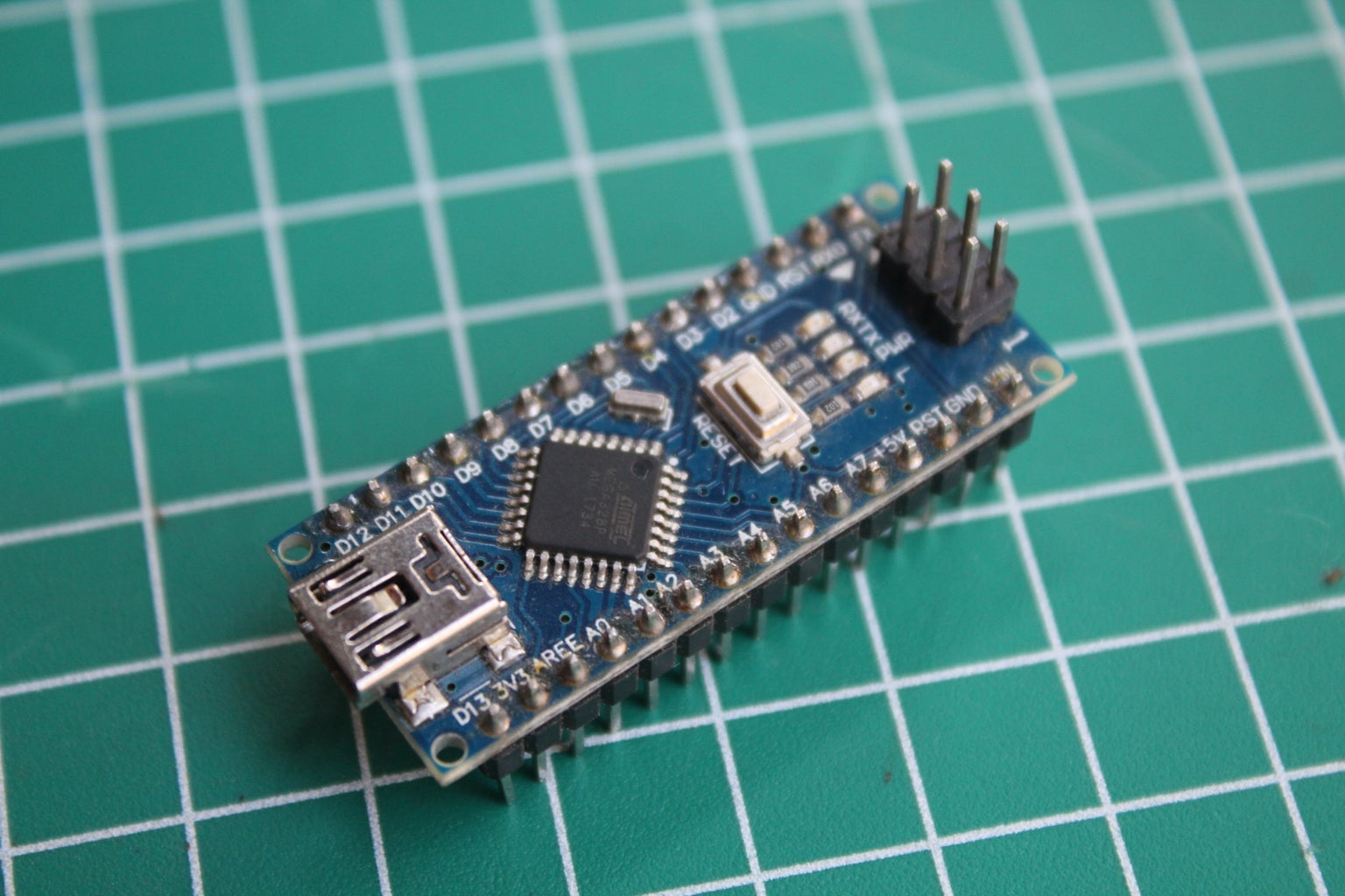
- Arduino Nano
- Jumper Wire
- USBmini
- Project Board
Required library:
- LedControl
Step 2: Scheme


To assemble the components see the schematic drawing above, you can also see the information below:
Led Matrix to Arduino
VCC ==> +5V
GND ==> GND
DIN ==> D6
CS ==> D7
CLK ==> D8
After completing the component assembly, proceed to the programming process.
Step 3: Programming

Use the code below to make a smile emoticon in the dot matrix:
#include "LedControl.h"
/* Now we need a LedControl to work with. ***** These pin numbers will probably not work with your hardware ***** pin 6 is connected to the DataIn pin 8 is connected to the CLK pin 7 is connected to LOAD We have only a single MAX72XX. */
LedControl lc=LedControl(6,7,8,1);
unsigned long delaytime=100;
void setup() { lc.shutdown(0,false); lc.setIntensity(0,8); lc.clearDisplay(0); }
void smile(){ byte a[8]={B00000000,B01100110,B01100110,B00000000,B00000000,B01000010,B00111100,B00000000};
lc.setRow(0,0,a[0]); lc.setRow(0,1,a[1]); lc.setRow(0,2,a[2]); lc.setRow(0,3,a[3]); lc.setRow(0,4,a[4]); lc.setRow(0,5,a[5]); lc.setRow(0,6,a[6]); lc.setRow(0,7,a[7]); }
void loop() { smile(); }

Step 4: Result


For the results can be seen in the picture above.

![Tim's Mechanical Spider Leg [LU9685-20CU]](https://content.instructables.com/FFB/5R4I/LVKZ6G6R/FFB5R4ILVKZ6G6R.png?auto=webp&crop=1.2%3A1&frame=1&width=306)


