

Introduction: Compact Protoboard Arduino Type Thing Yea


This ible is for the building of my small, almost matchbox size, arduino compatable board.
As seen in this ible.. https://www.instructables.com/id/Pocket-Ardiuno-kit/
I experemented with the one in this ible to see how it can be impreoved, but the consept is the same and so is the build to a degree.
Origonally made as a pocket board for taking places with a few components for messing with.
Basic specs:
- atmega168/8/328
- TTL interface
- 5V lines
- reset button
- power LED
- Digital and Analog pins
- Lilypad or normal bootloader (depending on chip and weather u have a crystal or not)
Options: (depending on the setup you are making it for)
- 9V input and 7805 regulator for 9V battery power
- Crystal/oscilator for non lilypad bootloader
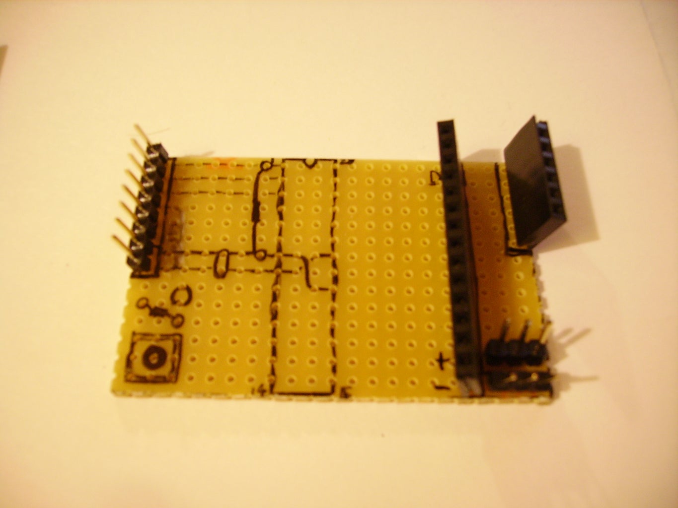
Pictured is the origonal used in the linked ible.
But for this ible i shall be running through the process by building a new one just for you :3
Step 1: Parts and Tools

You will need:
- Protoboard (i used the 3 hole strip type, but may be easier with full strip)
- 28 pin DIP socket
- 1K resistor X 2
- 1 x LED
- 1 x .01uf capacitor
- 1 x 8 pin header (5v and TTL)
- 1 x 12 pin header (digital pins)
- 1 x 6 pin header (analog pins)
- 2 x 4 pin header (power rail)
- 1 x pushbutton
- wire (i got mine from an old printer cable. lots aof wire and lots of colours ;) )
Optional:
- 1 x 16 Mhz Crystal or resinator/oscilator
- 2 x .01 uf capacitors (only if using crystal, but you may get away with not using them)
- 1 x Diode 1n4001
- 1 x 7805 regulator
- 1 x .01uf capacitor (for regulator)
- 1 x 9V battery clip
Tools:
- Soldering iron
- Solder
- flux (its good S**t :3 )
- clippers of some kind (for cutting wire and legs.. not your legs tho, that would be bad.. cut the component legs.. :P )
- helping hands type thing or another pcb holder for soldering
Step 2: Prep the Board...

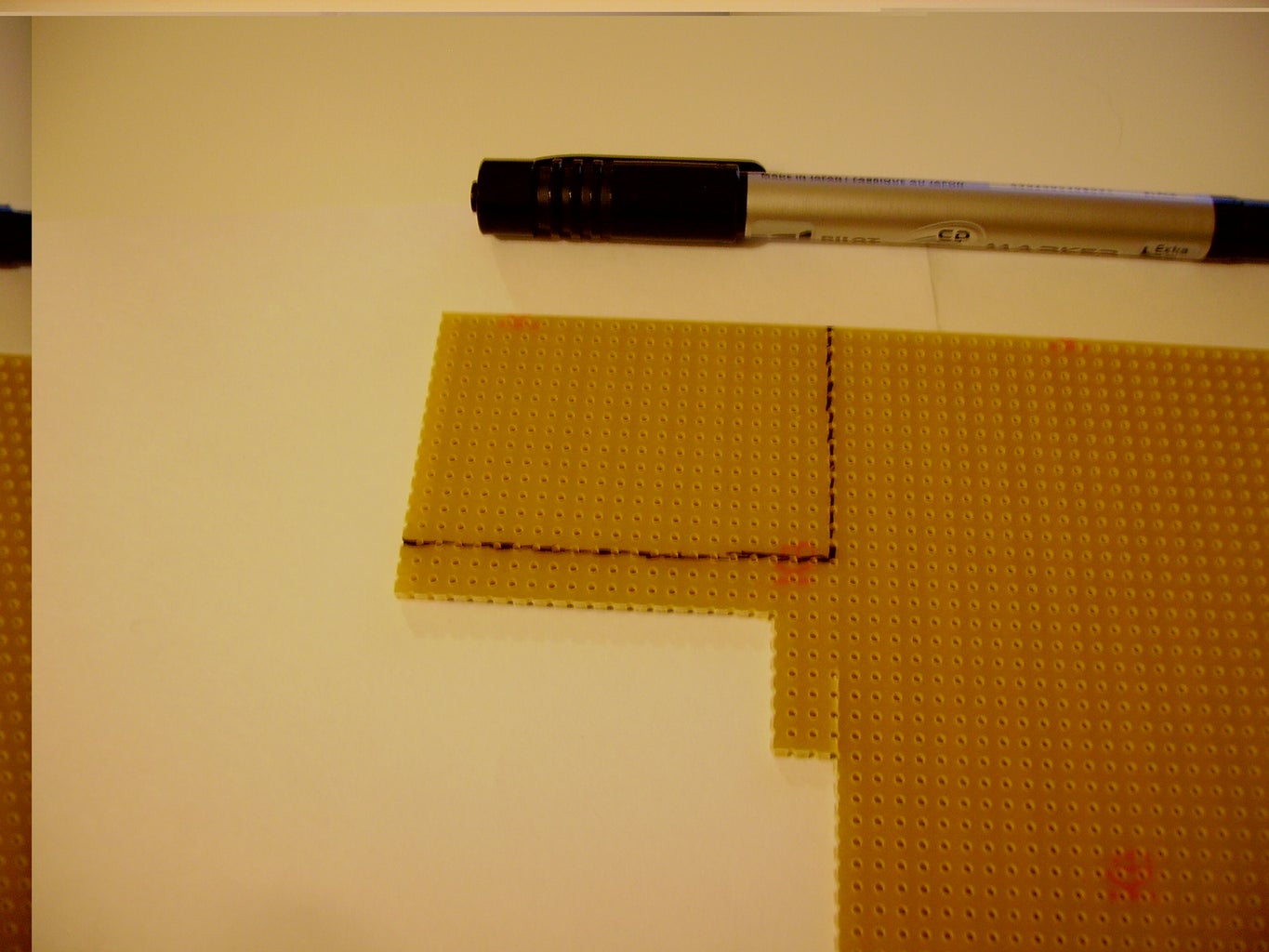


1st cut a board 14 x 21 (hole count x and y) make sure its clean.
If using stripboard and not the 3 hole strip kind then you will need to cut tracks in places..
*Plan out the placement of parts before you do this*
Mark up the board where you will be placing parts.
Step 3: Begin to Solder Up...


Begin by preparing the headers. cut them to size.
Then prep spot for the chip socket..
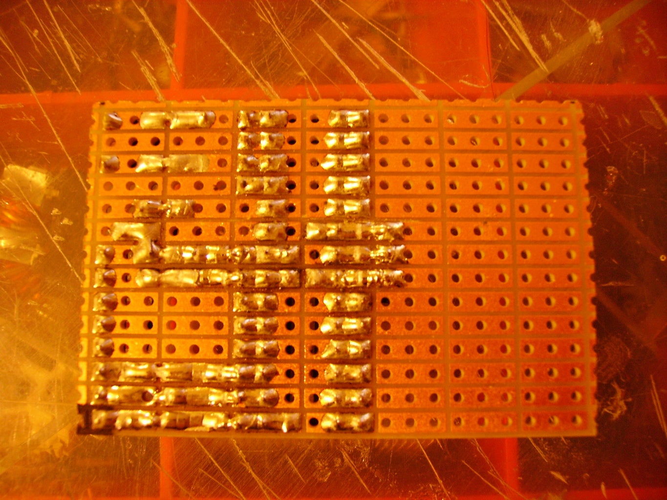
Solder in a 1k resistor between pin1 of the chip socket and the +5v pin 20.
Join up the vcc pins (7 and 20) on the topside of the board with a small bit of component leg to the resistor leg, make sure it doesnt intefere with the chip socket placement.
NOTE: Check schematics to be sure.
Bridge the GND pins (8 and 22) with insulated jumper wire over the resistor leg as shown in the pics.
Then place and solder the chip socket in place.
Step 4: Reset, and Power


Solder in a capacitor between the pins 7 and 8.
Next solder in a LED and 1k resistor on the same track as the LED+ as shown, and join the resistor to the Vcc, and bridge the LED- to the gnd track next to it.
Using jumper wires, solder next to the button (as shown in pic) and run one to RST and the other to GND. Then solder in the button making sure it is the right way round or you will have your board in perminant reset ;)
Step 5: Digital and Analog Headers..
Next we solder in the power and TTL header, there is seperate gnd and +5V as well as the ones on the TTL so u can power the board and power the TTL to RS232 converter from the board.
once that is soldered u then join the +5V on the ttl connectors to the +5V on the connector next to it, and the same with the gnd.. The seperate power connector liines up with pins 7 and 8 on the chip, the same goes for RX, TX and RST (see pic)
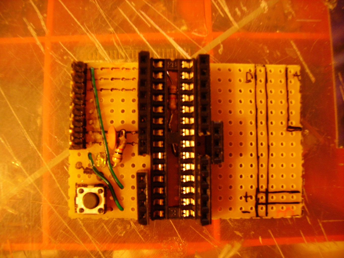
Solder in the digital pins and the analog pins headers. This time around i decided to do something different as i was using female headers..
Instead of weaving wires through the board to the pins on the other side i soldered the headers in right next to the chip socket.
and there you have it, basically its complete :) plug in a chip with the relevent bootloader and test.
Note: {if you plan to use this board for a specific function or project then u can use the blank portion of the board for other components or a chip (like a motor controller maybe)
I have a board with the chip soldered on like this that i have put into a smal robot, only the pins i need are on the board and a H bridge pair is soldered in too as a daughter board.}
Step 6: Optional and Additional

You can use available space left over to squeeze in a 9V input and a 7805 regulator with a diode for power feedback prevention. this isnt too hard but may require careful planning beforehand to make sure you use the available space well.
If you want to keep the space around the chip free then place the header pins over on the empty space like i did with the older model, (pictured in the intro) though this wil require many wires to link up the relevent pins.
I have added the pinouts of the atmega168 to arduino pins here
WARNING! Breadboard your project 1st in case something is wrong. i discovered some bugs after i soldered that had not happened on the previos model... nothing major though.
a: my LED kept shutting off after a while for some odd reason, make sure you have the right type. (tho this may be caused by the induction problems)
b: for some unknown reason i am getting power thru the aref pin (no chip in socket so its not actually connected to anything) this might be the power bridges under the chip socket causing induction. again breadboard and test fully.
Maybe one or 2 more capacitors on the power lines may clean this up
so yea.. far from perfect but you get the idea ;)
It works fine as u can see from this vid :)
It should work fine tho so breadboard it 1st unlike i did XD


