

Introduction: Cyborg Zombie Evolution


This Instructable is a tribute to the following great Instructables:
zombie friend?
Cat Burglar Joule Thief
Give the gift of Robot Invasion
and to the simple fact Instructables are great source of inspiration.
At Evil Mad Scientist you can find a circuit diagram and an explanation on how the joule thief actually works. Another explanation on this blocking oscillator (more correct according to some) can be found here.
When making the cyborg zombie in a workshop with children you should do some of the steps in preparation depending on their age and experience. For 6-year-olds I do step 2 to 4 in advance. More experienced young builders can do it all by themselves.
Step 1: What You Need


I grouped what you need in three separate short lists: the "good" (the zombie stuff), the "bad" (the joule thief electronics) and the "ugly" (the no soldering connecting stuff).
For the zombie you need the stuff described in the zombie friend? Instructable, minus one eye-thing. In short:
- a glove,
- stuffing
- something to use as an eye (e.g. a button)
- (embroidery) thread
- (embroidery) needle (size 18 or near)
- scissors
For the cyborg eye you need:
- a blue or white LED
- 5 cm of thin shrink tube (e.g. 1,2mm shrinking to 0,5mm diameter)
- 2N3904 transistor
- 1kOhm resistor (brown-black-red)
- 2 times a good 30 cm of thin single strand wire (Cat5e network installation wire works great)
- a toroid bead with an inside diameter of about 7 to 10 mm. You need it to be high inductance type, made for low frequencies. I learned white/green types for high frequencies do not work. White/yellow ones do. A common source are computer power supplies or Solid Core Ferrite Suppressors for round cables.
Update: the black "RT145-103-080" ferrite toroids available at Conrad (order nr. 508039) work very well, even with loose and unregular windings made by children.
Further, to connect all this you will need:
- 2 strong small nickled magnets with holes in them, e.g. nr. 503755 at Conrad or from a magnetic lock as used in jewelry. If soldering is no problem you can use the more common nickled neodymium magnets without holes.
- 2 times about 20 cm of single strand wire. I prefer them to be slightly thicker than the wire mentioned above, therefore I use some old fashioned telephone installation wire, but some more network wire can also be used.
- a piece of connecting block with four contacts, for fine wires (the type for 0,75 mm2 to 1,5 mm2 is OK)
- a screwdriver fitting the connecting block
- needle nose pliers
- permanent markers in four different colours
- a metal saw and if available a bench-vise
- a small piece of plastic sheet e.g. (5 x 10 x 0,5 mm, see next step)
- some (hot melt) glue (and hot melt gun)
- and finally a 1,5 V battery or 1,2 V rechargeable (for first tests, best make sure it is not a really completely dead one)
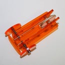
Step 2: Some No-soldering Electronics


Instead of soldering you will be sawing, glueing, bending, cutting and screwing.
Saw through the middle of one of the connections of the connecting block (a bench-vise is handy). Clean out the sawing dust by blowing in the cut ant glue in the small piece of plastic sheet with (hot melt) glue.
Bend the legs of the transistor as shown. If your transistor has no EBC marking, you can work it out following the picture, knowing the leads should still be in the same order if it is the same type (in other cases check the datasheet). Bend the B(ase) backwards and C(ollector) forwards. Taking in account the dimensions of the connecting block, bend the end of these two legs down again. Cut the E(mitter) slightly longer than the bent down ends of the other legs.
Slide the transistor legs in the connecting block, making sure the B(ase) is in the connection cut through. Screw tight the C(ollector) and E(mitter), making sure the transistor legs take hold. Put in one lead of the resistor with the B(ase) leg of the transistor and screw tight. Bend the resistor well away of the transistor legs and towards the remaining contact, were you attach the resistor's other lead.
side).
Step 3: Magnets and Wires


Magnets provide a "universal" way to connect to the battery.
From the 20 cm wires, remove about 2,5 cm of isolation. Make a loop around the mid section of the needle nose pliers. Reposition the loop between the ends of pliers and slide the wire through the loop, making a knot. Cut the short wire end even shorter to a couple of mm and bend it back parallel with the long wire end. Slide the wire through the hole of magnet. If your magnet has a cavity, press the knot into it. It does not matter if it slides back at this time, the zombie's arm will prevent that later on. Repeat with the second 20 cm wire and the second magnet.
If you do not get hold of magnets with holes in them, you might consider drilling holes yourselves. This is however quite difficult because magnets are very hard and quite of brittle. And it is a real pain to remove the chips, as these are of course all little magnets pulled towards the main magnet.
So, if you do not get hold of batteries with holes in them, soldering is the easier option. Nickled magnets solder reasonably well, but you have to put enough heat in them. You will probably put them on a steel surface to do the soldering. This works well but bear in mind that a massive piece of steel might drain to much heat from what you put in with your soldering iron.
Step 4: Colour Coding


Take out your permanent colour markers! But before you start marking, first strip all remaining wire ends of their isolation for about half a cm.
Put some shrink tube on the LED's legs.
Mark the wire ends with permanent marker as shown in the picture.
Mark the connection block, on the opposite side of the transistor: red at connection running through to the C(ollector) of the transistor , blue at the E(mitter), green at the resistor and black at the connection cut through, where the B(ase)-resistor connection sits at the other side.
Step 5: Cutting, Stuffing and Stitching a Zombie


From this point on making the zombie is child's play.
How is wonderfully well exlaind in this Instructable. So I will not try to do any better. Just leave out one eye, in order to replace it with the cyborg eye.
You can also drop the stitching to keep the arms upright. I found this was the only stitching that was difficult for young children to do themselves. Instead, our electrical wiring will allow us to bend the arms in the desired position.
You run one of the wires with a magnet attached through each arm. You can use a large needle as shown. Insert the wire at the "palm" and have it come out at the back of the shoulder. Pull the wire until the magnet fits snugly in the palm and with the needle nose pliers make a knot at the shoulder to keep it "under tension". You can twist the two wires a little to keep them together where they come over the shoulders towards the face of the zombie.
Step 6: Cool Coiling!


Now we get to make the cyborg eye.
When using network installation cable you can keep the wire pair twisted together for easier coiling of the toroid. The coiling is pretty obvious, but to make sure you can check it out in this instructable.
Put the leads of the LED through the wound toroid and connect the wires following the colour codes on the connecting block. When putting two or more wires in one connection twisting them together a little, before putting them in a connection, can help.
Test it with a battery you know is good, by attaching one "magnet-palm" to one contact of the battery and another to the other. As you do not have polarity markings on the magnets, make sure you try both ways. Also make sure the magnets are well on the battery contacts, not on the housing.
When it works it is a probably good idea to apply hot melt glue to strengthen the assembly. I did not do this myself, in order to find out how durable it is without. The first couple of cyborg zombies, Frank and Stien, were adopted by my play with my daughter a couple of weeks ago, and their cyborg eye still shines brightly. I must add that my daughter is rather careful with her toys/friends.
Step 7: Surgery Time


Before implanting the cyborg eye, make sure your zombie is adequately restrained. You assess the need for anesthesia.
Make an incision at the location of the missing eye. Depending on the stuffing you might need to remove some to comfortably fit in the connecting block. Close the incision with the stitch you prefer, with the toroid on the outside outside.
Step 8: It's Alive!

Feed the cyborg zombie its first battery and see how it brings the spark of life/light into its eye!
So how does this fit in the "Battery Powered Contest"? Well, for starters it is a fun way to drain the last life out of your primary batteries before recycling them and replace them by rechargeable batteries.
However, as this cyborg zombie is likely to be adopted as a guardian protecting a child's room against less cute cyborgs, zombies and other monsters, after a while you'd better feed it rechargeable batteries.
Note on the on the use of "draining circuits" like the joule thief on rechargeable batteries: normally discharging rechargeable is preferably limited to a 1 or 0,9 V. I did not find any information on just how harmful discharging to lower voltages, actually is to modern rechargeable batteries. It is however clear that many applications also drain the batteries lower than 0,9 V, without any obvious damage on the short term (e.g. solar garden lights). Anyway, polarity reversal, always reported to be really harmful, is excluded as we are working with a single cell.
Step 9: The Workshop


19 children aged 7 to 11 participated in the workshop I gave at Leefschool Klavertje Vier in Nevele, Belgium. With the help of 4 friends (many thanks!), we guided the children through making each their own cyborg zombie in under three hours.
It was great to see how the children made their own version and came up with some very clever ideas to make good use of the pieces cut from the gloves: a spare battery bag, a tail, a nose, skirts, trousers and even a bra…
Check out the pictures!
First Prize in the
SANYO eneloop Battery Powered Contest
Participated in the
SANYO eneloop Battery Powered Contest
Participated in the
Halloween Contest

![Tim's Mechanical Spider Leg [LU9685-20CU]](https://content.instructables.com/FFB/5R4I/LVKZ6G6R/FFB5R4ILVKZ6G6R.png?auto=webp&crop=1.2%3A1&frame=1&width=306)


