

Introduction: DIY AUTOMATIC SOLAR CHARGE CONTROLLER


Hello friends
Today I am back with another project called DIY AUTOMATIC SOLAR CHARGE CONTROLLER.
It’s an automatic switching circuit that used to control the charging of a battery from solar panels or any other source. It’s a 555 based simple circuits the charge the battery when the battery charge goes below the lower limits, and stop charging when the battery reaches it's upper limit voltage
Step 1: My Goal


“To make a cheap and efficient solar charge controller”
Step 2: Circuit
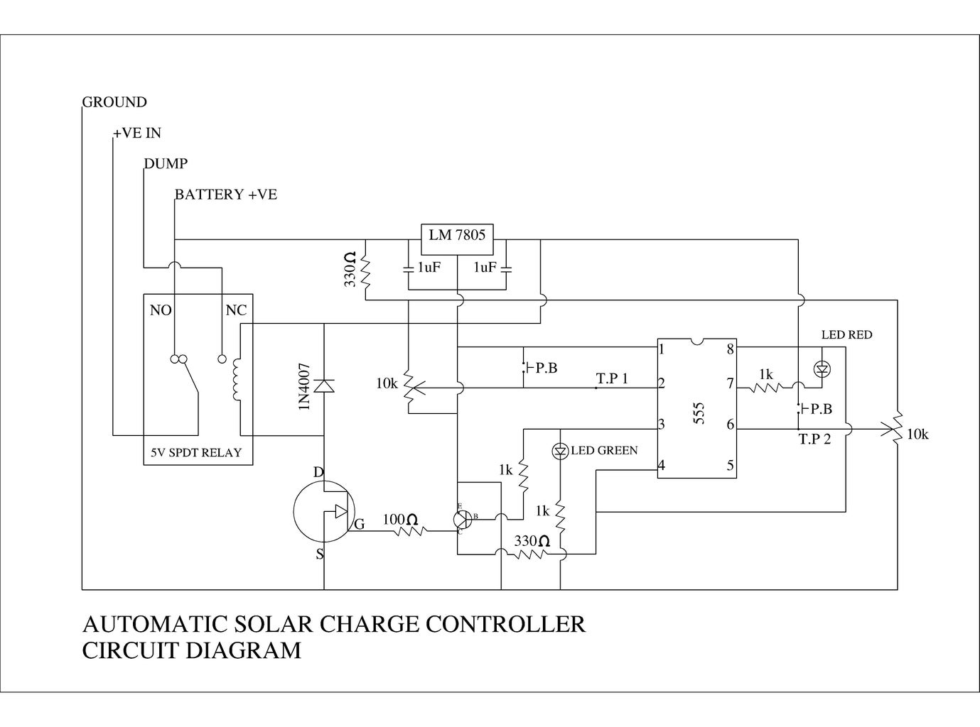
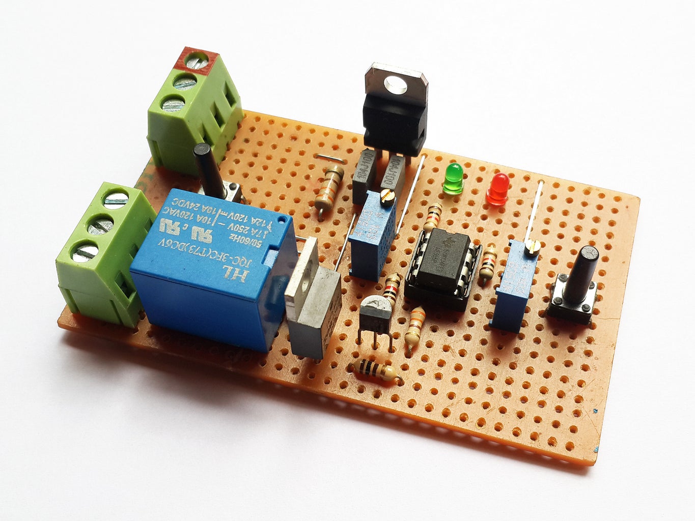
This is the driving circuit of the DIY AUTOMATIC SOLAR CHARGE CONTROLLER.
To make this circuit you need
1. NE555 IC with IC holder
2. One 2N2222 or PN222a Transistor
3. Three 1K Ohm resistors
4. One 330 Ohm & 100 Ohm resistors
5. Two 330 Ohm 1/5 w resistors(optional)
6. Two 10K variable resistor
7. Two LEDs (green & red)
8. 1N4007 Diode
9. 5V SPDT relay
10. two, 3-Pin PCB connector
11. Wires
12. PCB
13. LM7805 (TO-220 type)
14. Two capacitors(i am using .1uF,you can use any)
15.IRF 540 MOSFET
This is the finished circuit (Fig)
The 5v relay is the main component of this circuit; it’s an SPDT (Single Pole Double Throw) relay. It have one common (pole) terminal and 2 contacts in 2 different configurations. One is N.O (Normally Open) and other one is N.C (Normally closed)
In our case we connect the +ve of the solar panel to the pole of the relay and +ve of the battery to N.O when the battery is connected to the SCC (solar charge controller) the circuit check the battery voltage the voltage is less than or equal to lower limit the current is flows to the battery and battery start charging. When the battery voltage reaches the upper limit, the rely is activated and the current is redirect to N.C for dumping
Step 3: Calibration
After finishing the circuit you need to set the upper and lower limits. Batter calibration is required to avoid the overcharging and over discharging of the battery. I am using 12v as lower lower limit and 14.9v as upper limits. that means when the battery charge reaches the 12v battery start charging.wen the battery voltage reaches the upper limit or 14.9 volt .the relay is activated and circuit start dumping
To set the limits you will need a multimeter and a variable power supply or two power supplies. one with 12v and other one with 15v.first you will need to set the lower limit. for that set the voltage to 12v and connect it to the circuit. connect the ground weir to the conmen of the multimeter and touch the testing probe to the pin 2 of the 555 IC. Adjust the voltage by adjusting the VR to get 1.66 volte. Then set the voltage to 14.9v and touch the probe to the pin 6 of the 555 IC. adjust the voltage to 3.33v.check once aging .now over SCC is ready for use
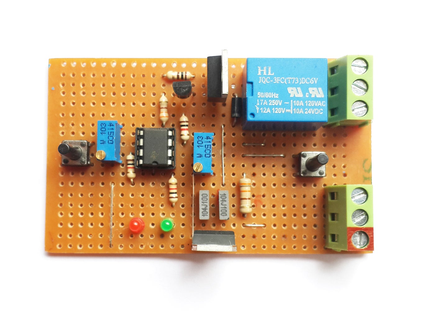
Step 4: Wiring

The Fig show the wiring diagram of the SSC
First connect the +ve from the solar panel to the centre pole of the relay then connect a red wire from battery to N.O of the relay. connect the –ve wire from the solar panel to the -ve of the circuit then connect the battery’s–ve to the circuit.
Step 5: Working
when the battery voltage is less than 14.9 v the it start charging by passing current through N.O of the relay. when the batteries voltage reached 14 volt its automatically switch the relay to N.C.if you are using solar panel you don't need an dummy load to dump the excess power. you can add an extra battery to the N.C to harvest the excess power
Step 6: Moment of Truth
this is a quick video of the DIY AUTOMATIC SOLAR CHARGE CONTROLLER
Step 7: Thank You
I will give thanks to you Mr. Mike Davis. this DIY AUTOMATIC SOLAR CHARGE CONTROLLER is based on the his design. I just modified it a bit to make it more compact. I will give all credit to Mr. Mike Davis

Third Prize in the
Solar Contest 2016

Participated in the
Circuits Contest 2016

Participated in the
LED Contest


