Introduction: D.I.Y NORMAL CLOSE SAFETY LOCK
The idea of this small project is to make a normally closed - electromagnetic safety lock that can be controlled by mobile phone through WIFI/4G network. Even if without a power source, the safety lock will still remain in locked state due to force from 3 contact blocks at back side of lock.
Please see video below and read the next steps to know how I can build this lock.
Step 1: B.O.M
The picture below includes all parts using for this project.

The main devices are as follows:
- Electromagnetic coil: I reused 24VDC magnetic coil from broken lock at scrap yard. Another way, for most of the solenoid valve, the solenoid valve coil is set within the valve body. It is separable and we can reuse it in case valve is in broken but solenoid coils is still in good condition. For example:

- Industrial contact block: 2NC (Normal Close) contact block and 1NO (Normal Open) contact bock.
- Small acrylic sheet.
- Wires, Bus 3, Bus 4, DC Power Jack Socket.
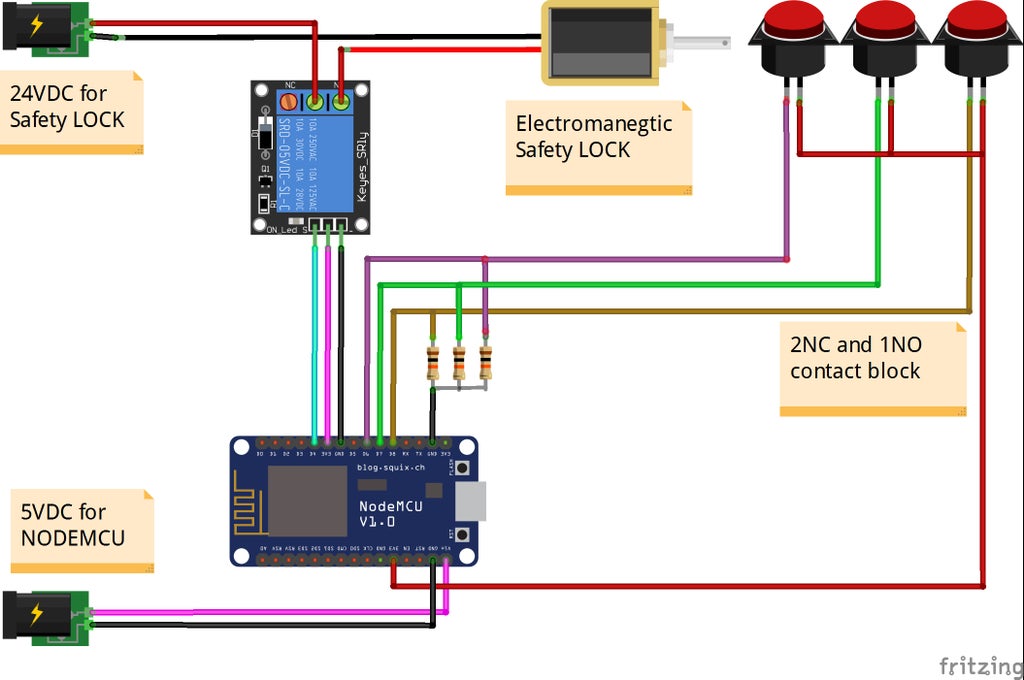
Step 2: SCHEMATIC
It is simple schematic diagram as below.

Step 3: ASSEMBLY
- Electromagnetic coil modification: A round aluminum plate is mounted in back side of magnetic coil to push the contact blocks when the magnetic coil is energized. When the magnetic coil is released, in the opposite direction the contact block will push the magnetic bolt to ensure the lock is in normal closed state. In both cases contact blocks will send 3 feedback signals to confirm the lock/ unlock status.

- Contact blocks: I used 3 contact blocks (2NC and 1NO) from Siemens and glued them tightly onto the small acrylic sheet, then soldered their pins to bus 4.

- Coil with contact block: With 2NC and 1NO contact blocks, they will handle the following functions:
- Feedback the operating states (lock/unlock) of safety lock.
- With 3 contact block, they are strong enough to push magnetic bolt and keep the magnetic lock in normal close state when it is locked or no power supply.
Sometimes during the operation, the lock will not CLOSE or OPEN as expected and these feedback signals will notify the correct state of the lock for safety reason.

- Installing relay module

- Soldering control board: Following the schematic on previous step, I soldered NodeMCU with some headers, 24VDC & 5VDC plugs. With this control board picture, I did not prepare to connect 3 contact blocks to the NodeMCU.

Step 4: FINISH SAFETY LOCK
After connecting the parts according to the schematic on Step 2, I have completed the hardware for the safety lock. Of course, this is just a trial test version with an acrylic body and it is for sure the control board should be located somewhere far away from the lock around a few meters.
Step 5: FIRST TESTING

I tested this lock by using the software named "iNut" from my friend. It is available at Apple Store and Google Play store:
- Android link: https://play.google.com/store/apps/details?id=com...
He donated me a firmware iNut i1. This is really cool firmware & application, now my safety lock can be controlled via WIFI/ 4G network (or via voice) by multiple phones as in the video clip.
To be updated....
THANK FOR YOUR WATCHING!!!

Participated in the
Trash to Treasure


