

Introduction: Digital Output


It's time to start programming! The first step is learning digital output, if you need a refresher on what digital output means, check out the Introducing the Microcontroller lesson. In this lesson, you learn how to build and program your first circuit using the LilyPad USB and Arduino IDE. You will learn how to navigate the software, some basic functions of an Arduino sketch and light up some LEDs.
You will learn:
+ basic functions of an Arduino sketch
+ what a variable is
+ how to turn on and off an LED and other digital devices
Step 1: Description + Materials

Download the attached file. This contains the final example sketches. These are only for reference and if you get really stuck. Follow along and you will learn how to get to the final sketches on your own.
+ microcontroller
+ USB cable
+ 2 x sewable LED
+ alligator leads
Attachments

Step 2: Setup in Arduino

By now you should have the Arduino IDE along with any drivers downloaded and installed on your computer. This was gone over In the Introducing the Microcontroller lesson. If you haven't done this, scroll down the Getting Started with Arduino page to where it says "Install the Arduino Software". Choose your computer's operating system and follow the instructions.
Once you have Arduino downloaded and installed open the application.
Plug in the LilyPad USB board using a micro USB cord. Before you can upload a sketch to the board, you need to do two things
1)Choose what board you are using.
In the software navigate to:
Tools > Board > LilyPad USB
2)Choose what port to communicate through.
In the software navigate to:
Mac
Tools > Port > /dev/cu.usbmodemXXXX
Windows
Tools > Port > COM X
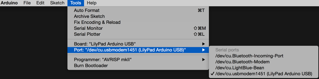
The software will hint to you which port to use by listing the board's name next to it. This is very convenient. With older versions of Arduino, this does not occur. If you do not see your board's port, uninstall the drivers and install them again, close the Arduino application and reopen.
You are now ready to build a circuit and start uploading sketches to your board!
Step 3: Introducing the Sewable LED

The 5mm domed LEDs are the ones most recognized, but LEDs come in all kinds of shapes and sizes. For wearable electronics, sewable LEDs are available. They work the same as the other LED, but come flatter, with a smaller diode and they have a built-in current limiting resistor. So, there is no need to add one!
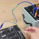
Step 4: Build Circuit

Before connecting anything to the board, turn the power switch toward CHG. This prevents the board from getting power from your computer. Always make connections when the board isn't powered.
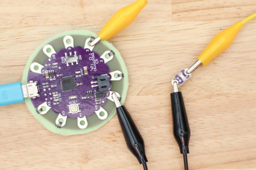
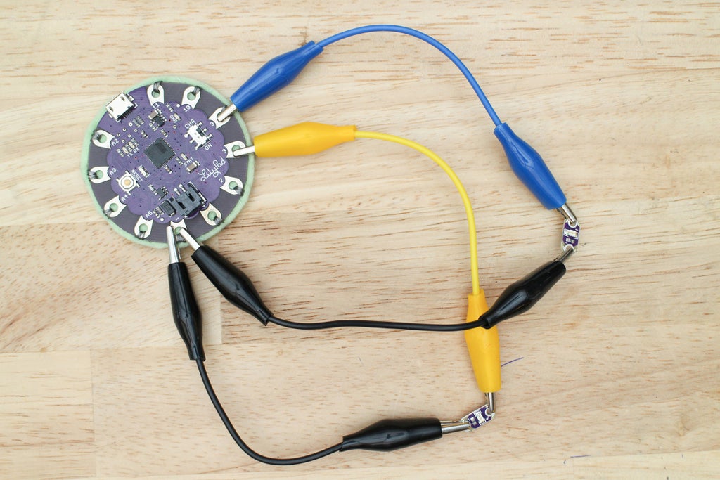
Grab the alligator leads and use them to make the connections between the LED and the microcontroller as shown.
LED power (+) --> pin 3 LilyPad
LED ground (-) --> ground (-) LilyPad
Step 5: Open Sketch

The Arduino IDE comes with a lot of built-in example sketches to work with. You can find these in the Examples folder located under File. This is a good place to start and get snippets of code to learn and build from. Arduino has excellent support on the forums and lots of documentation to learn from on their website, which I will continue to link to throughout the next few lessons.
To open your first example sketch, navigate to:
File > Examples > Basics > Blink
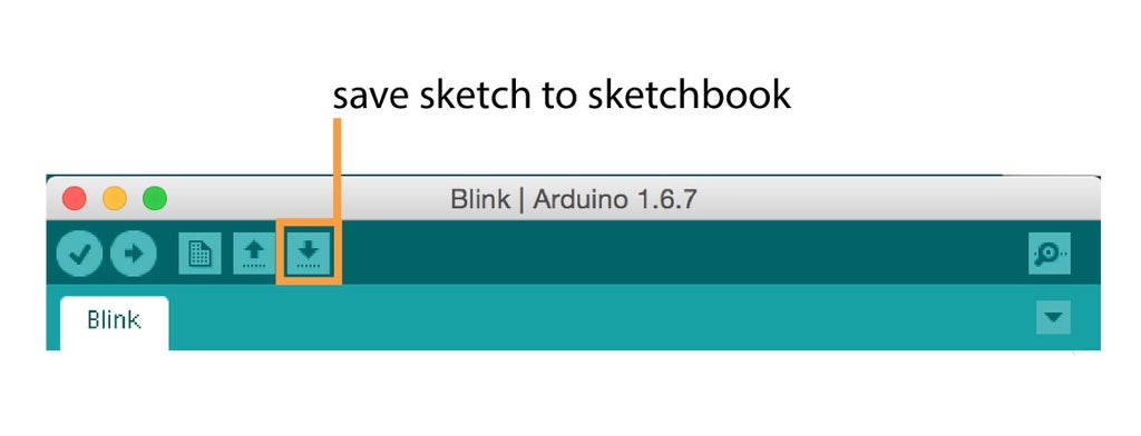
Copy and paste the example sketch in a new window and save as BlinkDemo. When you save a sketch it is saved to your Sketchbook which is found by going to: File > Examples > Sketchbook
Step 6: Define LED Pin Number

The example Blink is a popular first sketch to upload to a board for the first time. This is because it's a simple sketch that is an excellent way to be introduced to Arduino and programming basics.
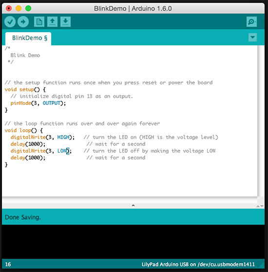
Before you upload the sketch there is one thing that needs to be changed. In a sketch, you need to define what pin number your component is connected to in order to read and write to it. Start by looking at what pin you clipped your LED on, then look at the sketch and notice that the example's pin is defined as 13. Your LED is connected to pin 3, so every time it says 13 in the sketch, change it to 3.
Step 7: Upload

Turn the board on and check that your port and board chosen under Tools. In the sketch window, press the button with the arrow pointing to the right to upload the sketch. 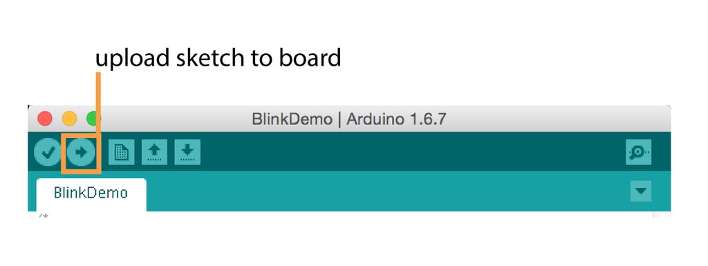
Once the button is clicked, Arduino will verify your code, looking for syntax, spelling, and other errors. It will then upload it to your board. You will see an error print out at the bottom if there is something wrong with your sketch. If there is an error, open a new Blink sketch and compare it to yours, looking for discrepancies. You may have accidentally erased something while copying and pasting, or forgotten to change your pin number.
Once uploaded, you will get blinky success! The LED will blink on and off every second.
Step 8: Formatting From Here on Out
As mentioned in the Welcome lesson, you will upload a sketch first, then I will explain what the code does afterwards under the sections titled "The Code".
For each sketch, I will call out and explain what a new part of the sketch is doing. My explanations will be relatively short, but will link to a reference page on Arduino's website for deeper diving. The explanations will be a mixture of my own wording and excerpts of the important points taken from the reference pages.
I will explain what each line does above the snippet of code and expand on new pieces of the sketch. Some repeating parts of the code will not always be reviewed, but new parts will be.
Step 9: The Code: Formatting From Here on Out

When you work with Arduino sketches, you will work with functions. They are an essential part of most programming languages. Go and read the function reference page on Arduino's site.
The definition of a function from the reference page:
"Segmenting code into functions allows a programmer to create modular pieces of code that perform a defined task and then return to the area of code from which the function was "called". The typical case for creating a function is when one needs to perform the same action multiple times in a program."
The Arduino language has built-in functions for you to use that execute code in the background. In a sketch, Arduino will automatically color code built-in functions by making them orange.
Below are some of those built-in functions. I've summed up what they do in this sketch and have linked to the reference pages on Arduino's website. Don't worry about reading through all the references that are linked to now, you will get more familiar with these functions through using them throughout the class.
setup() + loop()
There are two functions that make up an Arduino sketch; the setup() and loop() functions. Most of your code will go within these two functions.
Setup() only runs the code within it once after each powerup or reset of the LilyPad USB. Use it to initialize variables, pin modes, serial port, etc.
void setup() {
  pinMode(ledPin, OUTPUT);
 }
Loop() does what the name suggests, it loops through the code within its curly brackets which allowing your program to change and respond; for example, being able to read sensors continuously and then turning on an LED with the sensor hits a certain value. Use it to actively control the Arduino board
void loop() {
  digitalWrite(ledPin, HIGH);
  delay(1000);
  digitalWrite(ledPin, LOW);
  delay(1000);
}
Now, let's take a look at some of the built-in functions that are used within setup() and loop().
PinMode()
pinMode() declares a pin is an output or input. Here it's saying that pin 3 is an output.
pinMode(3, OUTPUT);
DigitalWrite()
The digitalWrite() function is used to set the pin on the Arduino to high (5V), or low (0V). This function takes the pin number and the value (HIGH or LOW) as it's arguments.
digitalWrite(3, HIGH);
Comments
Arduino ignores lines of text that start with two forward slashes; this is called a comment. Comments make the sketch easier to read for you and others later on. Change the comment above the pinMode() command to reflect your changes.
//initialize digital pin 3 as an output.
Delay()
To blink the LED, create a pause using the delay() function. This function takes time in milliseconds as it's argument. Here the time is 1000 ms, which equals 1 second.
delay(1000);
Step 10: Declaring a Variable

The number 3 is used a few times in the blinkDemo sketch. What if we wanted to change the pin number later on? We would have to change all three instances. The number 3 isn't very descriptive either, we could be using 3 later on in a simple mathematical operation and it could get confusing. In this sketch, 3 is the pin our LED is on. What if we could just name it and define it once? That would make it easier to change later on. We can, if we create a variable! Other than functions, variables are a very important part of programming, and darn useful too!
A variable can be thought of as a cup that a piece of data (the number 3) is stored in. A name is written on the outside of the cup (ledPin is a good name!), which we can then use to reference the piece of data it contains. Variables also tell the computer what kind of data it is dealing with, so it can act accordingly.
To declare a variable in your sketch it must have a type, name and value.
int ledPin = 3;
int is short for integer (meaning whole number), which is the type of data.
ledPin is the variable's name we gave it; make it descriptive!
= is how we assign the name to a piece of data.
3 is the data we are assigning to the variable name.
There is another piece of code that is used when declaring our ledPin variable. Const appears in front of the variable when you know that the value will not be changed later on. This helps protect it from being unintentionally reassigned as the program grows.
const
So, go ahead and add this new line of code at the top of your blinkDemo sketch as illustrated above.
const int ledPin = 3;
One thing is left to do. Since the name ledPin now references the number 3, replace the instances of the number 3 with your new variable name. Save your changes.

Step 11: Upload

Upload the sketch. It will give you the same results, the LED will blink every second. The difference is that you are now using your shiny new ledPin variable! If you get an error go back and check the line of code.
Does it have a semicolon at the end?
Is it outside of your setup() and loop() functions? Why would you want it outside of those anyhow? The answer is to make them global variables. We won't get into that in this class, but if you want to learn more go here.
How are you doing? A lot of the explanations about the code are for reference and fundamentals you should know if you are to continue with Arduino. But the real learning is from experimenting with code, uploading, and seeing what happens. If the code explanations are feeling a bit heavy; build the circuits, upload the code and come back the code definitions later.
Step 12: Add a Second Output

You've got one LED going, let's make it more interesting and add a second.
With an LED still on pin 3, make these new connections:
LED power (+) --> pin 9 LilyPad
LED ground (-) --> ground LilyPad
Step 13: Create the Sketch

Copy and paste your blinkDemo sketch in a new window and save it as blink2LEDs.
See if you can figure out how to add the second output LED on your own. Look at the provided blink2LEDs sketch if you get stuck.
Add the necessary code to complete these steps in order:
+ create variable
+ set pin as output
+ turn on led
+ pause for period of time
+ turn off led
*hint - you can copy and paste all your needed code from the existing sketch.
Step 14: Upload

Upload the blink2LEDs sketch and the two LEDs will blink in unison. Experimenting with the code is the best way to learn how it works.
Experiment:
Try these two things to get different behaviors:
1) alter the delay() function to make both LEDs go on for 2 seconds and off for half of a second
2) alter the digitalWrite() function that affects the ledPin2 variable to get the LEDs to blink at different times

Step 15: Test Your Knowledge
{
    "id": "quiz-1",
    "question": "A sewable LED has a built in... ",
    "answers": [
        {
            "title": "Transistor",
            "correct": false
        },
        {
            "title": "Resistor",
            "correct": true
        },
 {
            "title": "Capacitor",
            "correct": false
        }
    ],
    "correctNotice": "That's correct",
    "incorrectNotice": "That's incorrect"
}
{
    "id": "quiz-2",
    "question": "This is an example of a function.",
    "answers": [
        {
            "title": "HIGH",
            "correct": false
        },
        {
            "title": "const ledPin = 3;",
            "correct": false
        },
 {
            "title": "delay(1000);",
            "correct": true
        }
    ],
    "correctNotice": "That's correct",
    "incorrectNotice": "That's incorrect"
}
{
    "id": "quiz-3",
    "question": "When declaring a variable, what does “=“ character do?",
    "answers": [
        {
            "title": "It means “equal to”",
            "correct": false
        },
        {
            "title": "Assigns the name of the variable to a piece of data",
            "correct": true
        },
  {
            "title": "It's the data type of the variable",
            "correct": false
        }
    ],
    "correctNotice": "That's correct",
    "incorrectNotice": "That's incorrect"
}
{
    "id": "quiz-4",
    "question": "The setup() function...",
    "answers": [
        {
            "title": "Loops continuously",
            "correct": false
        },
        {
            "title": "Runs once when the LilyPad USB is poweredup or reset",
            "correct": true
        },
{
            "title": "Is where you should always put your variables",
            "correct": false
        }
    ],
    "correctNotice": "That's correct",
    "incorrectNotice": "That's incorrect"
}
Step 16:
How did you do? Share your blinky circuit using the blink2LEDs sketch below! The experiments are extra credit.

![Tim's Mechanical Spider Leg [LU9685-20CU]](https://content.instructables.com/FFB/5R4I/LVKZ6G6R/FFB5R4ILVKZ6G6R.png?auto=webp&crop=1.2%3A1&frame=1&width=306)


