

Introduction: ESP8266 BASIC IoT Light


This Instructables show how to use ESP8266 BASIC remote control a household light.
Step 1: Why Remote Switch?

My home hall light switch hide behind the Cabinet and far from the door. It is hard to turn on the light when I came home or turn off the light when I leave. So I want to control the light remotely.
Before do that, here are some concern about the remote switch:
- other people may gain the access to control the remote switch too
- remote receiver normally consume power below 1 W, but it run in 7x24 basis, so it still use up some extra power
- it may have some risk being shocked while accessing AC power
After evaluated the concern, I still want a remote light switch, so I go to next step.
Step 2: Turn Off the Main Power Before Any AC Access


For safety reason, you should switch off and double check no AC current before access any AC wire.
Step 3: Check Wires in the Switch Socket

Same as many remote receiver, ESP8266 require a DC current to operate, so I need a AC/DC converter. However, in some case, the switch socket may only have the Live wire but did not have the Neutral wire. In this case, it cannot provide DC current in the socket.
After checked it have both Live and Neutral wire in the socket, we can keep going to the next step.
Step 4: Choosing Remote Receiver
There are many cheap remote light switch in the market, but I guess it is very easy to jam other home remote channels.
ESP8266 use WiFi connect to my own AP with encrypted signal should be good enough.
There are still many firmware support ESP8266: NodeMCU, Arduino, MicroPython, ESP8266 Basic...
ESP8266 Basic have a very good feature, once I flashed the firmware, all program work in web base. That means I can hide the board in the socket and no need to take out for reprogram. (except upgrade firmware :P)
ESP8266 firmware ref.:
Step 5: Preparation


- ESP8266, any version should be OK, this time I am using ESP-07
- A USB FTDI programmer for flashing ESP8266 Basic firmware
- A light switch socket with USB charge plug (for AC/DC conversion)
- A 10 k Ohm resistor
- A 2N2222 transistor
- A 3 V / 250 V 3 A relay
- Few wires for AC circult
- Few wires for DC circult
- A 3 pin Screw Terminal Block Connector
- A 5 V to 3.3 V DC/DC convertor
and it need some hot glue and clear tape for insulation
Step 6: Disassembly the Switch Socket
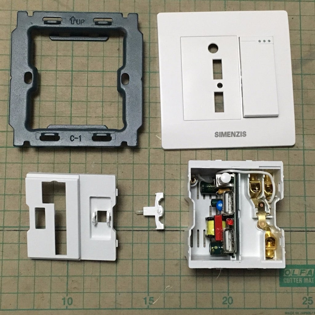
I need to connect the extra screw terminal block connector, squeeze my component in it, access the AC/DC converter and wire out the 5 V power source, so I need disassembly the switch socket first.
Step 7: Install 3 Pin Screw Terminal Block Connector


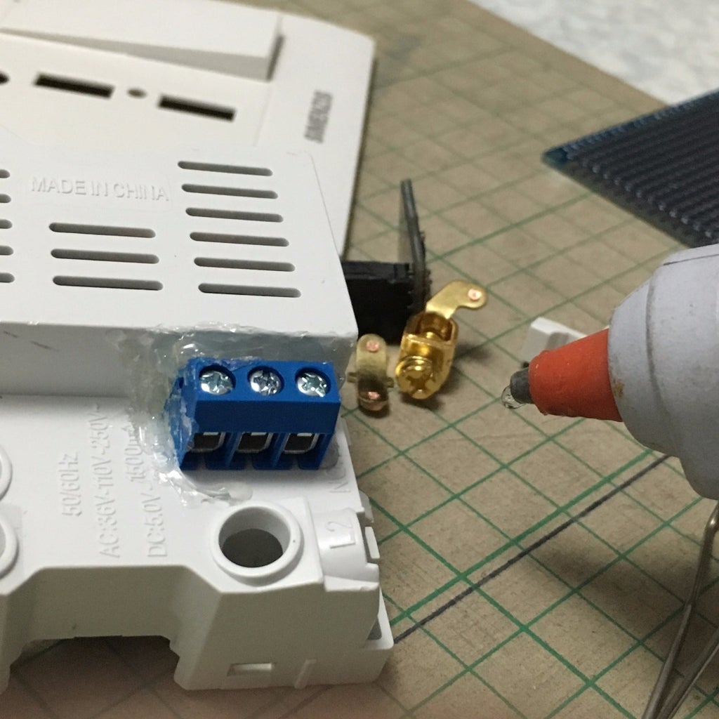
- Mark the Pin in the Socket
- Drill the holes
- use hot glue to fix the connector
Step 8: Program ESP8266 Basic
If you are using ESP-07 too, here is the connect reference:
ESP-07
- Tx -> FTDI Rx
- Rx -> FTDI Tx
- GND -> FTDI GND
- GPIO15 -> FTDI GND
- GPIO0 -> FTDI GND
- VCC -> 3.3 V
- EN (CH_PD) -> 3.3 V
After flashing ESP8266 BASIC, remember remove the GPIO0 connection and reset (simply re-plug the USB) for testing.
Ref:
Step 9: Connect and Config ESP8266 BASIC

After removing the GPIO0 connection and reset (simply re-plug the USB), you can search a WiFi AP called ESP by the mobile or notebook.
Connect to the AP ESP and open the URL http://192.168.4.1
Firstly, make it connect to the home WiFi AP:
- press [setting] link
- fill the AP name and password
- press save button
- before restart, open a serial console (Arduino have one) in the computer connected ESP through the USB FTDI programmer
- press restart button
- if everything goes right, you can see ESP connected to the home WiFi AP and show the current IP address in the serial console, remember the IP address
- try connect to the IP address with web browser
- it is recommended config the DHCP server associate fix IP address to the ESP device
Step 10: Simple Toggle Switch Code
I want the light switch can be controlled by both physical switch and web base interface, so I write a simple toggle logic to alter the GPIO output.
Here is my sample code, edit, paste and save to ESP8266 BASIC: (ESP will restart after save)
cls
let OutputPin = 5
button "Toggle" [Toggle]
wait

[Toggle]
if PinStatus == 1 then goto [On] else goto [Off]

[On]
PinStatus = 0
po OutputPin 1
wait

[Off]
PinStatus = 1
po OutputPin 0
wait
Step 11: Soldering Work


Here is the summary of the connection:
5 V to 3.3 V DC/DC convertor
- +/- IN -> USB charge panel
- +/- OUT -> ESP
ESP-07
- GPIO15 -> GND
- GND -> GND
- EN -> 3.3 V
- VCC -> 3.3 V
- GPIO5 -> 10 K Ohm resistor -> 2N2222 transistor base
2N2222 transistor
- base -> 10 K Ohm resistor -> ESP GPIO5
- collector -> relay coil terminal -> 3.3 V
- emitter -> GND
Relay
- Common terminal -> Terminal Block Connector
- Normally open terminal -> Terminal Block Connector
- Normally close terminal -> Terminal Block Connector
- Thanks to CaptClaude remind me it should put a diode parallel to the relay coil (ref.: http://music-electronics-forum.com/t4456/)
If you are using ESP-01, some points to be noted. Connect a NPN transistor to GPIO have a side effect that pull down the pin. ESP-01 only have GPIO0, GPIO2, Tx(GPIO1) and Rx(GPIO3), pull down GPIO0 or GPIO2 at power on will enter flash mode; connect 2N2222 to Tx also cannot start up normally. Hopefully it can still connect to GPIO3, everything can work fin.
Step 12: Insulation


Use hot glue to seal all AC connected parts and then use some clear tape to cover the DC/DC converter and ESP board.
Step 13: Re-assembly the Switch Socket

Squeeze all component to the socket and then re-assembly the switch socket.
Step 14: Replace the Old Socket


I want the light can control by physical switch and ESP connected relay, so it need to connect the switch and relay in serial.
Step 15: Test Connection
Ensure you mobile connected home WiFi:
- open the ESP IP address with the browser
- click [RUN] link
- press toggle button
- the light should turn on and off while you press toggle button
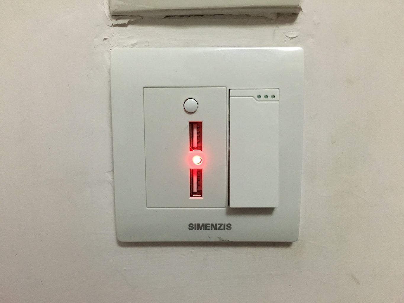
Step 16: Happy IoT!
This ESP8266 BASIC light actually only connected to the home LAN but not Internet, but it still can remote control the light outside the home if you have setup the home VPN.
If you really want your light become a real IoT, try Blynk, I have tested it works while research, just a little bit difficult than ESP8266 BASIC :P

Participated in the
Full Spectrum Laser Contest 2016

![Tim's Mechanical Spider Leg [LU9685-20CU]](https://content.instructables.com/FFB/5R4I/LVKZ6G6R/FFB5R4ILVKZ6G6R.png?auto=webp&crop=1.2%3A1&frame=1&width=306)


