Introduction: Easy Laser Cut Lantern
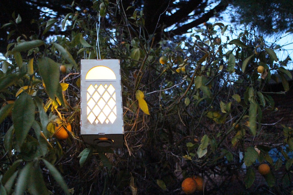
Few things set the mood more than outdoor lighting at dusk. While there are endless varieties available on the market, there's something about custom made things that really sets them apart from anything store bought. These LED lanterns were made with a diamond mesh, but really any shape can be cut into the lantern that you can imagine. Leaf shapes, yes. A name, yes. Dinosaur shapes, heck yes!
These lanters have a finger joint on the same that allow them to fit together in any number combination, meaning you can have a 3 sided lantern or a 30 sided lantern, the choice is yours! These lanterns were made using the free browser-based design program Tinkercad.
DISCLOSURE
Dremel was kind enough to loan me a laser to try out and see what projects I could come up with using Tinkercad. You can find out more about Dremel's new laser cutter and get a hefty discount here (discount ends September 30, 2018).
You can explore my design below, in the embedded Tinkercad interface
Ready to make your own custom lanters? Let's make!
Step 1: Reference
This project uses inexpensive LED candles with a flickering light. To make sure that the LED candle fits inside the lantern measurements were taken to get the diameter and height for reference. These dimensions will come into play when the bottom of the lantern is designed.
Step 2: Lantern Sides + Finger Joint
Open a new design in Tinkercad and drag a box shape onto the workplane. With the box selected, grab one of the handles on the corner and stretch out the box to a rectangle shape. I kept the measurements simple at 100mm x 200mm.
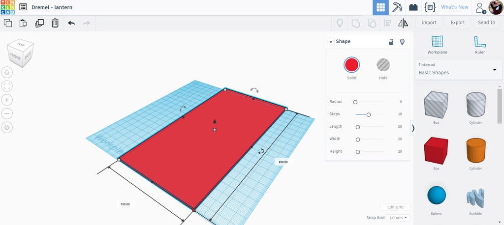
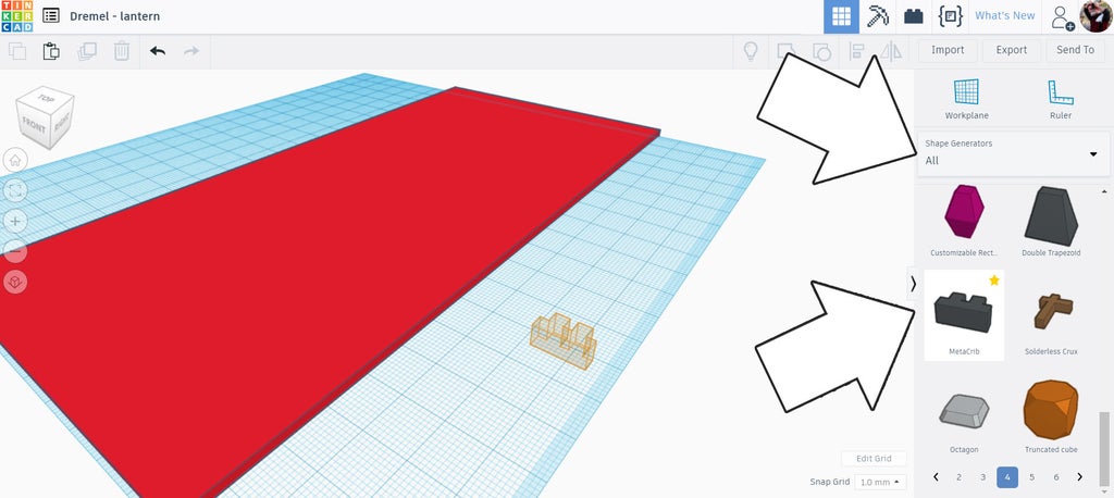
I changed the height to 4mm. When we export this file as a vector SVG the program will only export what ever is touching the workplane. Under the library dropdown on the right side of the screen I selected Shape Generators and chose All. There's a shape called metacrib which has a square oscillation that we can edit, perfect for the finger joints on the sides of this lantern. Drag a metacrib onto the workplane.
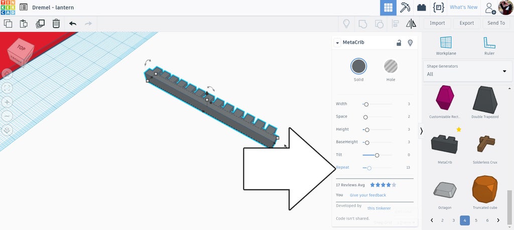
With the metacrib selected an option box appears that allows us to modify the parameter of the shape. THe bottom slider is repeat, which defines how many nodes there will be.
The top two sliders are width and space, which determine the width of the nodes and the space between them. Since we want these fingers to interlock these value need to be the same. I chose 15 for each.
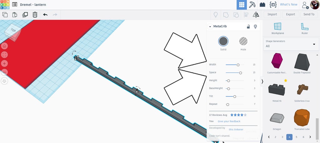
This produces a long finger joint that can be placed on one edge of the lantern side.
Step 3: Place Finger Joints
Rotate and move the metacrib overlapping the edge of one side of the rectangle, ensuring the space part of the metacrib is on the edge of the rectangle shape (only the finger part should protrude beyond the rectangle).
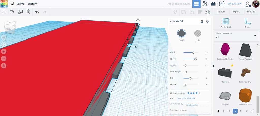
To make a matching finger joint we need to duplicate (ctrl+D) the metacrib shape and offset it one node width (15mm, in this design). This will allow the two metacrib shapes to interlock. To remove the tail on one end of the duplicated and offset metacrib I dropped a hole box over the end and grouped the shapes.
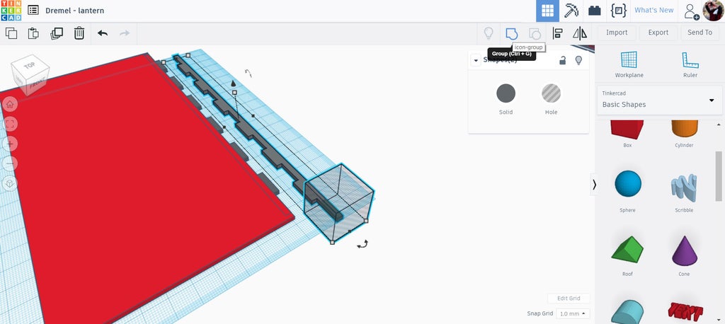
The duplicated metacrib was then flipped and moved over to the other edge of the lantern, ensuring that only the fingers of the metacrib protrude from the rectangle side.
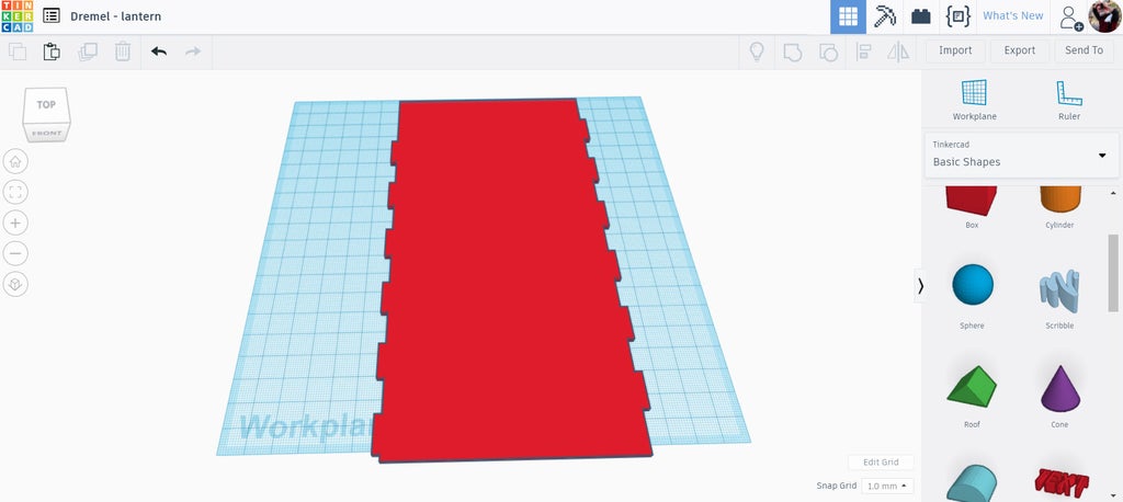
Group all 3 shapes (retangle and 2 metacribs) together to make the side of the lantern. Only one side piece needs to be designed, as copies of this shape will interlock into each other.
Step 4: Top + Bottom Notches
Notches were made in ends of this side panel to allow the lid and base to register correctly. Like the finger joints on the sides these notches are centered, which allow these pieces to be used in almost any orientation.
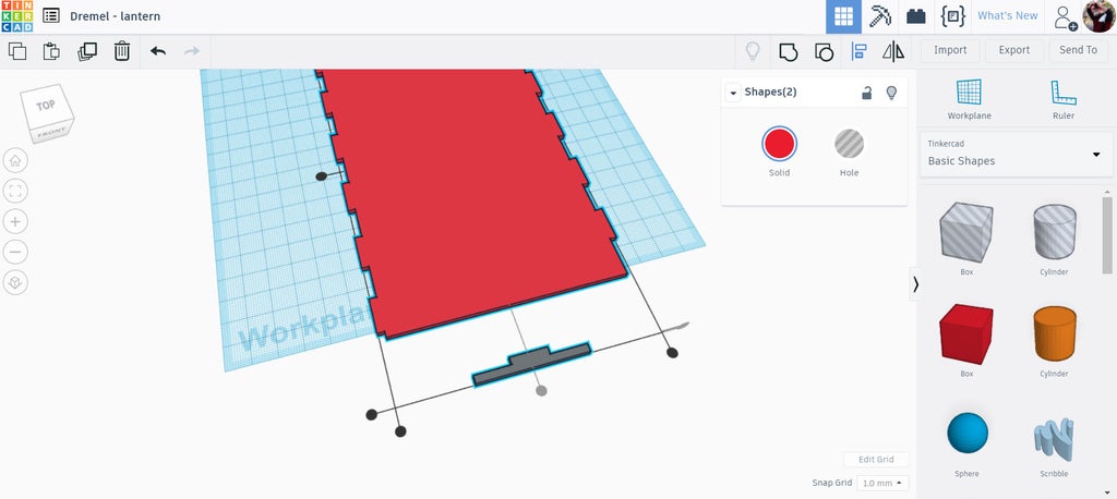
Using the metacrib again I used the same width and spacing as the sides, but only made one repetition so there was one node. I used the align command from the top toolbar to center the metacrib on the long axis of the side piece, then moved the metacrib so that the node was inside the side piece.
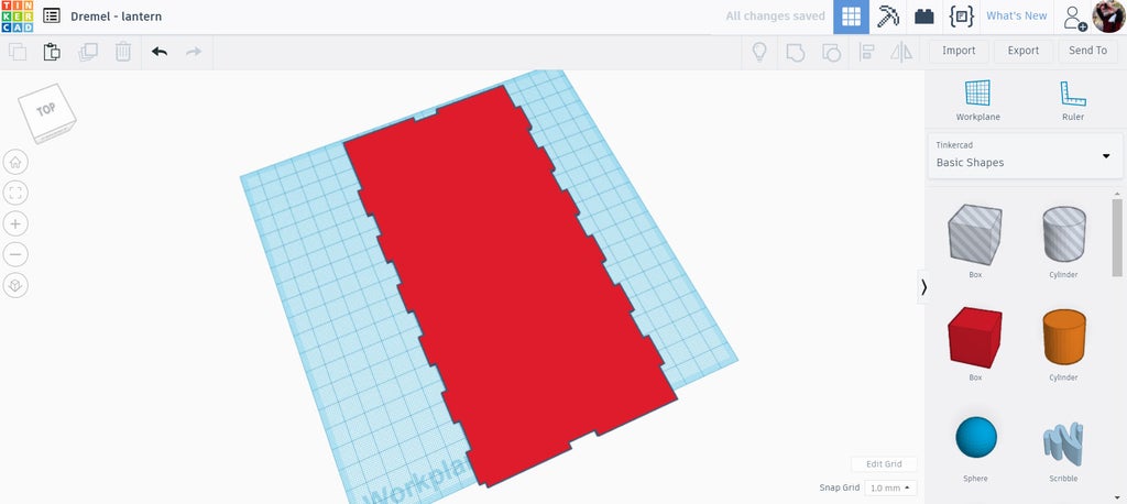
Finally, the metacrib was made into a hole so it would cut away a notch into the end of the side piece. The same process was used on the other end to create a notch on both ends.
Step 5: Top + Bottom Pieces
The top and bottom pieces were made in a similar fashion to the side piece. A box was dropped onto the workplane and then stretched with the corner handles to be 100mm x 100mm. Then, metacribs with a single node were centered on each side to create the notches.
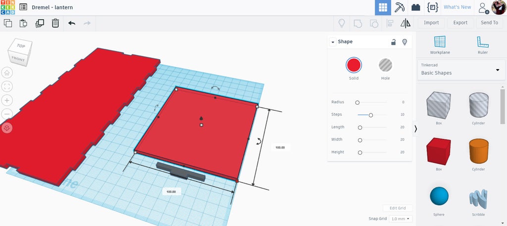
Once all four sides had metacrib notches added, ensuring that only the notch portion of the metacrib was protruding, the piece could be grouped together to make the piece. The top and the bottom pieces will have slight differences, so duplicate the grouped piece so there is a copy.
Step 6: Top + Bottom Pieces, Continued...
The top piece will have two small openings that will be used to hang the lantern from a piece of string. I used two hole cylinders from the basic shape library to make these. The cylinders were resided to be 2mm x 2mm, then positioned in the center of one of the end pieces, then grouped to make the openings.
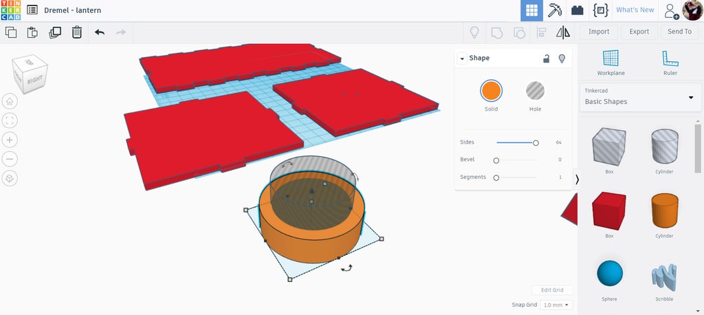
d
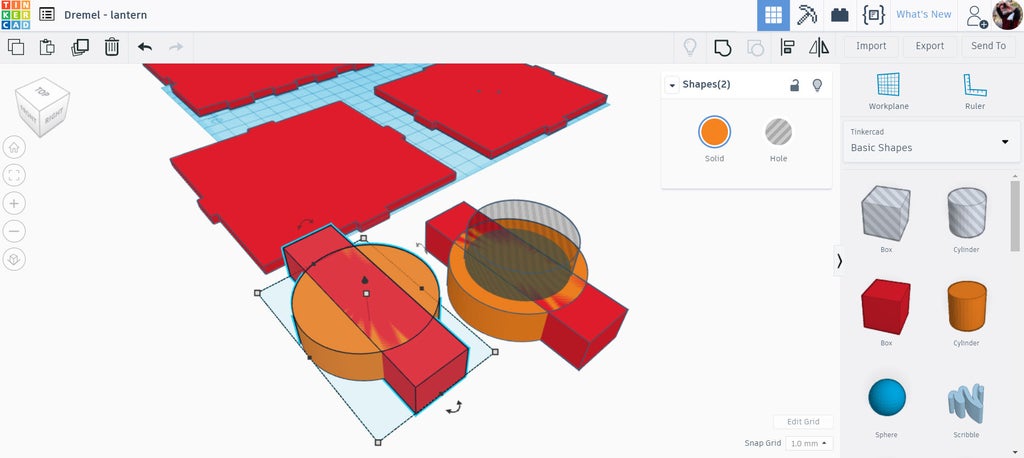
A box was dragged onto the workplane and stretched to be a rectangle, which was also aligned to be centered on the two cylinders. This shape will be grouped to be the holder of the LED candle.
A duplicate was made of the larger cylinder and rectangle and moved off to the side. This duplicate was changed to be a hole shape, which will be used to cut an opening in the bottom piece of the lantern that will match the LED candle holder shape.
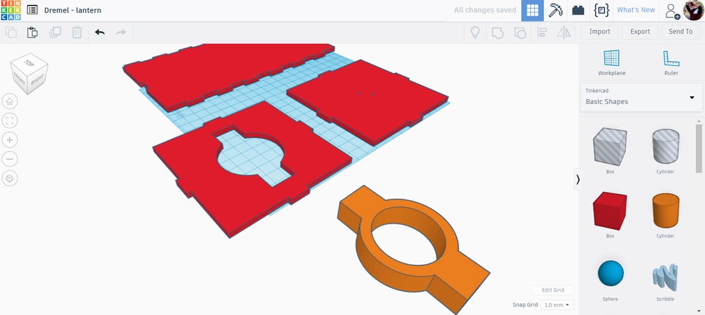
In the image above we can see the shapes after they have been grouped, the LED candle holder in the foreground and a corresponding shape cut out of the bottom lantern piece in the background.
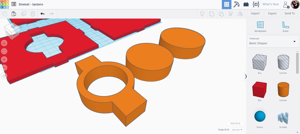
The LED candle holder will need support so that it doesn't fall through the opening in the middle. Two more cylinders were dragged onto the workplane, one was sized to match the diameter of the candle holder and the other was sized a few millimeters wider in diameter. When stacked together, the larger diameter cylinder will prevent the LED candle holder from accidentally falling into the lantern.
Step 7: Lantern Pattern
With the structure completed attention can be turned to the most interesting part, the pattern design of the lantern. The blank structure part of the lantern can be copied and saved for later, allowing as many variations of patterns and designs as you like.
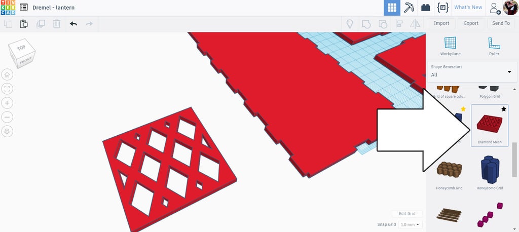
For this design I used a diamond mesh pattern that was found in the Shape Generator dropdown on the right side library. The mesh pattern can be modified one the shape is dragged onto the workplane.
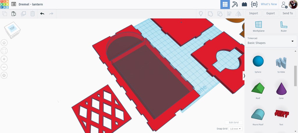
Before the diamond mesh can be added to the lantern there needs to be an opening. I used a box and round roof shape found under the basic shapes library top make holes in the lantern, using the align tool to keep things centered.
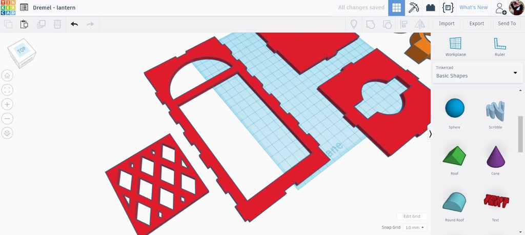
With the holes cut from the lantern the diamond mesh could be moved and stretched into the opening.
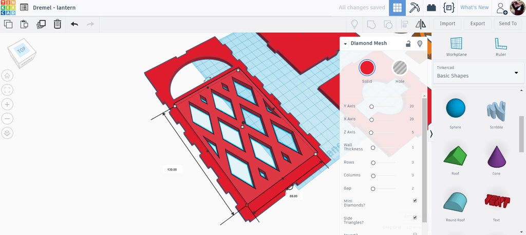
With the diamond mesh selected an option window pops up and sliders can be moved around to define the desired pattern. The diamond mesh and the lantern piece can then be grouped to make the shape.
Step 8: Export
Here are the pieces of this design ready to be exported. Remember that only the shapes that are touching the workplane will be exported as SVG vector files. For this design only one lantern side is needed as the SVG can be copied in the laser software to create more.
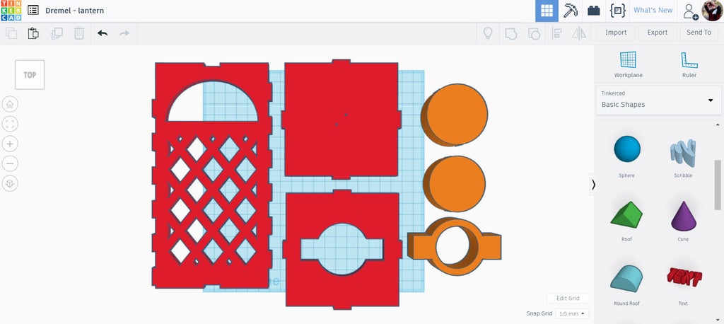
Select each piece individually and then export, choose the SVG for lasercutting in the pop up.
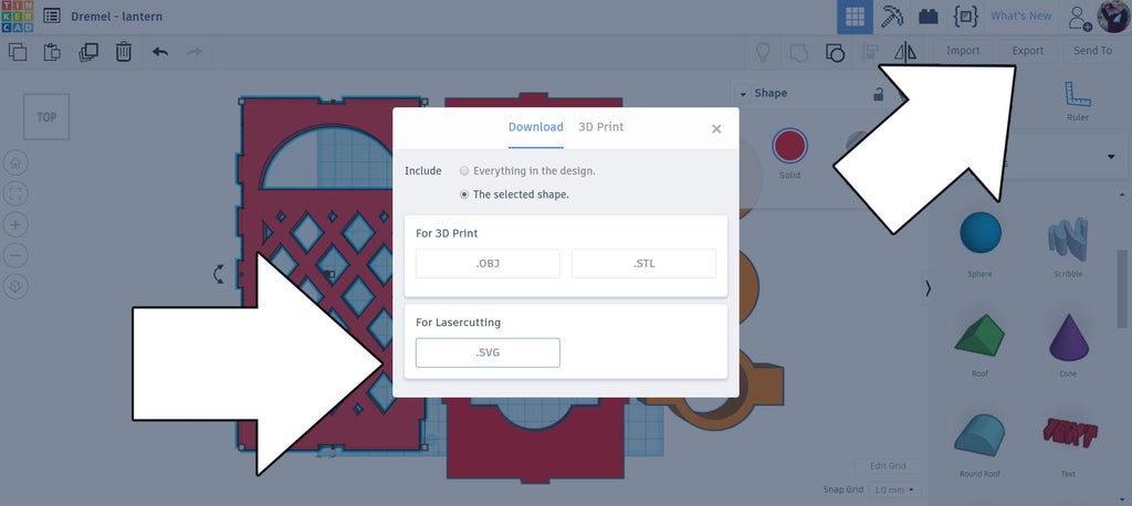
With the pieces exported they can now be cut with the laser cutter.
Step 9: Laser Time!
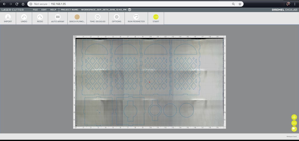
The Dremel laser interface was opened in a new browser window, then the SVG files were imported. I made a lantern with 4 sides, so the array option within the interface was used to create 4 copies of the SVG of the lantern side.
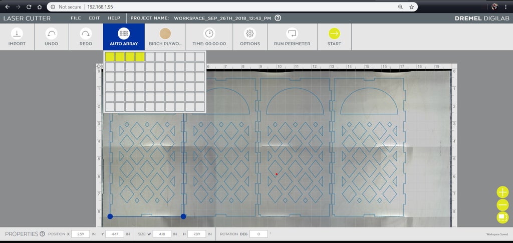
The array tool is great because it has a small offset between each piece without wasting any material. The remaining lantern SVG files were added and positioned on the material then cut out using the default options for Birch plywood at ⅛". The Dremel laser has these defaults already programmed, taking out the guesswork.
Step 10: Paper Insides
With large areas of the lantern cut out for the pattern there needs to be a layer behind the cutouts, both for appearance and for the LED light to diffuse onto. Tracing paper works well for this application.
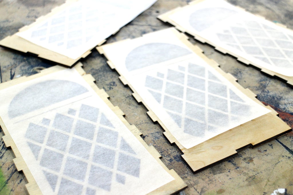
Rectangles of tracing paper were cut to match the area needed for each lantern face, then was glued in place on the backside of each lantern side and left to dry.
Step 11: Glue + String
After the tracer paper has dried the sides can be glued together. Carefully apply glue to the fingers on each side and glue up the lantern.The LED candle holder pieces can also be glued together now.
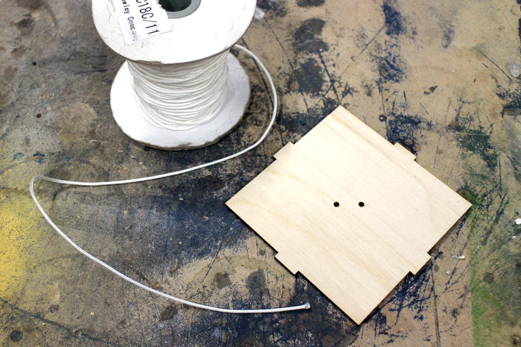
Feed a piece of string through the top piece openings and tie in a knot to make a loop. This will be what the lantern will hang from.
Glue the top and bottom to the already glued sides and let the glue dry for about an hour.
Step 12: Finishing
The lantern does look neat with the laser seared edges, but I decided to sand the fingers smooth and remove the char. I used a 120 grit in a random orbital to smooth over the edges and surface leaving things nice and smooth.
I finished the wood with a paste wax to give it some shine and prevent smudges on the wood from grubby fingers. This lantern will be suited for indoor use only (in my case it doesn't rain where I live, so it's safe outdoors).
Step 13: Shine On!
Wait until civil twilight and turn on your lantern.
This was an easy project to make and produces great results. Another way to make this lantern would be by adding a solar panel on top, allowing endless light at night from its daytime charge.
If you made a version of this lantern (with, or without a laser) I want to see it! Share a picture in the comments below.
Happy making :)


