

Introduction: Gesture Controlled Robotic Arm


Welcome to the instructable for a Gesture Controlled Robotic Arm.
This instructable has two parts. An instructable has already been written for the Robotic Arm called EEzyBotArm. You can access the instructable here- https://www.instructables.com/id/EEZYbotARM/
The value add that we at CuriosityGym did is that we built an easy interface to control the arm. We chose to use a couple of sensors and an Arduino to send gesture information to the Arm over Bluetooth. Want to build one? Lets get started.
Step 1: Making of the Robotic Arm
We chose a ready design for the mechanical parts and the Robotic Arm. Searching on thingiverse, we came across the EEzyBotArm http://www.thingiverse.com/thing:1015238
The Arm is also accompanied by an extremely detailed Instructable here https://www.instructables.com/id/EEZYbotARM/
We chose this arm because it has standard components like screws and nylock nuts, and was rigid, strong and could be replicated easily.
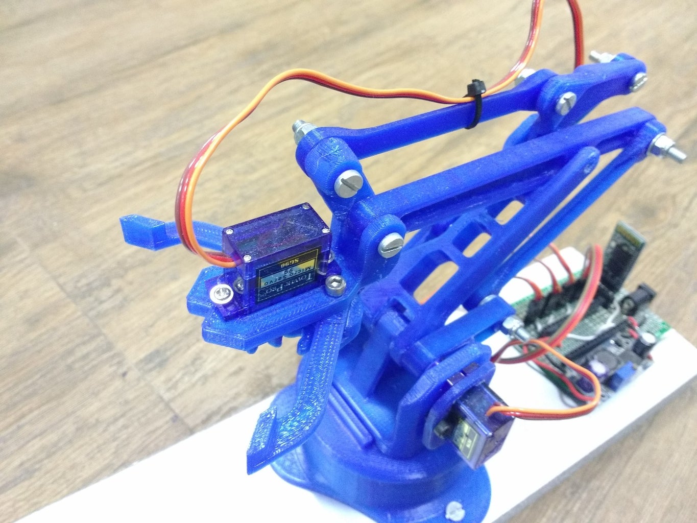
Step 2: Electronics for the Arm

We used an Arduino Nano for the brains of this project, alongwith a HC-05 Bluetooth Module for communication, and a LM2596 Buck Regulator Module to provide stable power to the servos, Arduino and the Bluetooth Module.
Driving the servos from the puny power regulator for the Nano is not advisable, A sudden movement can create a current surge and can reset the nano.
We used a SG90 standard servos with nylon gears, available cheapely in any DIY hobby or RC shop.
The power was provided by a 9v power supply running from the wall plug.
Please see attached the image for the connections between all the above components.
In the Photo above, S1, S2, S3 and S4 are servo motors. Mapping of these can be found in code.
Code for the Arm can be accessed here https://github.com/CuriosityGym/EEZyBotArm/blob/ma...
Step 3: Constructing the Glove


The Glove we used for this project was a simple glove used for cleaning purposes. It was made of cloth which made sewing easier.
We stitched the Flex sensors on the first and second fingers of the glove. A new circuit was soldered with a general purpose PCB with the following componenents
1) A 10 PIN FRC Male Connector
2) An MPU6050 IMU Sensor
3) Pins to connect the flex sensors and the resistors for them.
A second glove was inserted inside the first one to provide good stability and strength while removing and wearing.
Step 4: Glove Arduino Interface


The 10 pin FRC connector was used to connect to the Arduino wearable which was strapped on the wrist of the person controlling the glove.
Pins on the FRC connector connect the IMU and the Flex Sensors to the I2C and Analog interfaces of the Arduino.
A Bluetooth HC05 connects to the the Arduino which transmits information about IMU orientation and Flex sensor Bend magnitude via Bluetooth to the Robotic Arm.
Code for the Glove interface can be accessed here https://github.com/CuriosityGym/EEZyBotArm/blob/ma...
Please see attached the image of the schematic for the glove.
The instructions listed here http://www.technotroniks.com/jugaad/bluetooth-hc-05-to-hc-05-pairing-master-slave/ were used to pair the two HC05 Devices so there is no Arduino action required for pairing.

Participated in the
Arduino All The Things! Contest


